
Aluminum alloy pipe bend forming method

A bending forming, aluminum alloy technology, applied in the field of mechanical processing, can solve problems such as depression, protrusion, distortion, etc., achieve the effect of enhancing strength and hardness, moderate plasticity, improving processing efficiency and pass rate

Inactive Publication Date: 2014-06-18
GENERAL RESEARCH INSTITUTE FOR NONFERROUS METALS BEIJNG
View PDF7 Cites 29 Cited by
  • Summary
  • Abstract
  • Description
  • Claims
  • Application Information

AI Technical Summary

Problems solved by technology

[0004] The purpose of the present invention is to provide a method for bending and forming aluminum alloy pipes, so as to solve the problems of severe distortion in the section of aluminum alloy pipes after bending, such as depressions and protrusions, and ensure that the cross-sectional dimensions of aluminum alloy pipe bending parts can meet the design requirements , improve the processing efficiency and qualification rate of aluminum alloy pipe bending parts

Method used


Image

  • Aluminum alloy pipe bend forming method
  • Aluminum alloy pipe bend forming method

Examples


Embodiment 1

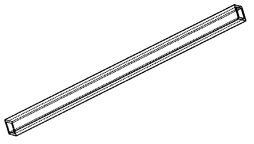
[0019] The material used in bending forming in this embodiment is an aluminum alloy rectangular pipe with a cross-sectional size of 14.1 mm*12.1 mm, a wall thickness of 1.4 mm, and a length of 1.5 m, such as figure 1 shown. The mass percentage of each element in the low melting point alloy is 6% cadmium, 17% lead, 23% tin, 3% zinc, 51% bismuth, and the melting point is 72 degrees. The specific steps of bending forming are as follows:

[0020] 1.1 Preparation of low-melting point alloys, the specific method is as follows: open the resistance furnace for smelting, place the prepared metal raw materials (purity above 99.9%) in the crucible of the resistance furnace, sprinkle diboron trioxide as a covering agent, and put the resistance Adjust the temperature of the furnace to 400°C-500°C. After the metal in the crucible is completely melted, stir the melt for 1-2 minutes, remove the scum on the surface of the melt and sprinkle with boron trioxide covering agent again, let it stan...

Embodiment 2

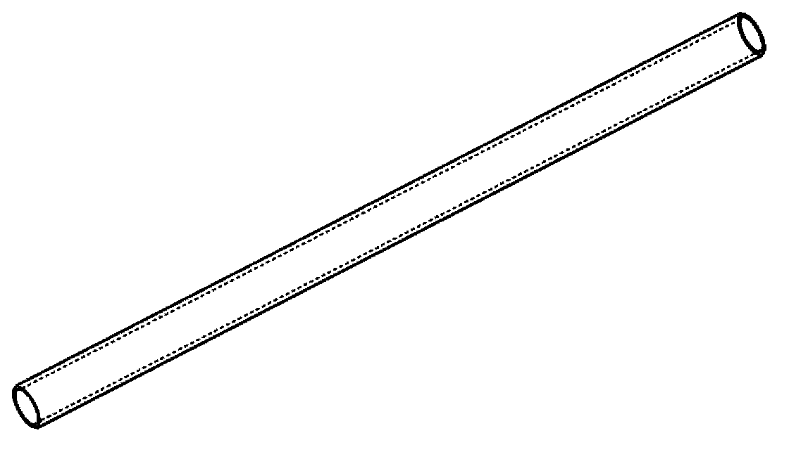
[0024] The material used in bending forming in this embodiment is an aluminum alloy circular pipe with a diameter of 13.6 mm, a wall thickness of 1 mm, and a length of 1.5 m, such as figure 2 shown. The composition of the low melting point alloy is 8% cadmium, 18% lead, 24% tin, 50% bismuth, and the melting point is 70 degrees. The specific steps of bending forming are as follows:

[0025] 2.1 Preparation of low-melting point alloys, the specific method is as follows: open the resistance furnace for smelting, place the prepared metal raw materials (purity above 99.9%) in the crucible of the resistance furnace, sprinkle diboron trioxide as a covering agent, and put the resistance Adjust the temperature of the furnace to 400°C-500°C. After the metal in the crucible is completely melted, stir the melt for 1-2 minutes, remove the scum on the surface of the melt and sprinkle with boron trioxide covering agent again, let it stand for 2-3 minutes and then remove it. The slag is ta...


PUM

PropertyMeasurementUnit
diameteraaaaaaaaaa
thicknessaaaaaaaaaa
lengthaaaaaaaaaa

Abstract

The invention discloses an aluminum alloy pipe bend forming method and belongs to the technical field of machining. According to the method, low-melting-point alloy is used as a filler to achieve internal pressure supporting, and bend forming with controlled section deformation is achieved. The method has the advantages that the low-melting-point alloy is used as the filler so that strength and hardness of a pipe are improved, problems of sectional serious deformation, such as deboss and embossment after bend forming of an aluminum alloy pipe are solved, the sectional dimension of an aluminum alloy pipe bent piece can meet design requirements, and machining efficiency and qualified rate of the aluminum alloy pipe bent piece are increased. Besides, low-melting-point alloy is adjustable in melting point temperature, alloy composition can be adjusted according to machining requirements, the plasticity of the low-melting-point alloy is moderate and not prone to break during machining, and bend forming with low-melting-point alloy as the filler is advantageous.

Description

technical field [0001] The invention belongs to the technical field of mechanical processing, and in particular relates to a bending forming method of an aluminum alloy pipe. Background technique [0002] Because aluminum alloy pipes have a series of excellent characteristics such as high specific strength, light weight, and good heat dissipation performance, their bent parts are widely used as structural parts in aviation, aerospace, ships, automobiles and other fields. , and the interior is hollow, etc., under the huge load of the bending forming process, under the action of tensile and compressive stress, the deformation is uneven, and serious cross-sectional distortion will appear, such as: cross-sectional depressions and protrusions, resulting in parts after bending. The circumferential surface is uneven, which cannot meet the cross-sectional shape and dimensional accuracy of the raw material. [0003] At present, there are some improvements in the bending and forming ...

Claims


Application Information

Patent Timeline
Patent Type & Authority Applications(China)
IPC IPC(8): B21D9/00B21D9/16
Inventor 杨银闫晓东
Owner GENERAL RESEARCH INSTITUTE FOR NONFERROUS METALS BEIJNG
Learn More