A regenerative braking continuously variable transmission for vehicles

A continuously variable transmission, regenerative braking technology, applied in transmission, fluid transmission, belt/chain/gear, etc., can solve the problems of large volume, reduced engine installed power, complex structure, etc. The effect of small installed power and improved stability

Inactive Publication Date: 2016-03-09
QINGDAO UNIV
View PDF9 Cites 0 Cited by
  • Summary
  • Abstract
  • Description
  • Claims
  • Application Information

AI Technical Summary

Problems solved by technology

[0003] The purpose of the present invention is to overcome the defects of large size and complex structure caused by the excessive dependence of the continuously variable transmission device, vehicle transmission system and technology on the planetary gear system, clutch, etc. in the prior art, and seek a design to provide a regenerative braking system for vehicles Continuously variable transmission, using hydraulic accumulator, electromagnetic switch valve, variable pump-motor and variable motor-pump for power transmission conversion, confluence and diversion, forming a continuously variable transmission with regenerative braking function, the driving force generated by regenerative braking The driving force of the engine or the electric motor does not converge and synthesize through the planetary gear system, and the power interruption, connection or speed change does not rely on the clutch. The driving force generated by regenerative braking can realize engine starting and vehicle driving, etc. The continuously variable transmission makes the engine Or the motor mainly works in the best economic working condition area, reducing the installed power of the engine, reducing the volume of the power transmission system, improving the efficiency of the power transmission system, and realizing the regenerative braking function at the same time

Method used


Image

  • A regenerative braking continuously variable transmission for vehicles
  • A regenerative braking continuously variable transmission for vehicles

Examples


Embodiment

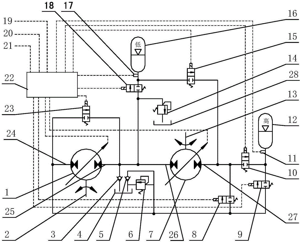
[0011]The main structure of this embodiment includes a digital variable pump-motor 1, an input shaft 2, a reverse fuel supply check valve 3, a first fuel supply tank 4, a vehicle feed fuel check valve 5, a reverse safety valve 6, a digital variable motor- Pump 7, direct connection electromagnetic switch valve 8, energy release electromagnetic switch valve 9, energy recovery high pressure electromagnetic switch valve 10, high pressure sensor 11, high pressure accumulator 12, output shaft 13, car entry safety valve 14, return flow electromagnetic switch valve 15 , low-pressure accumulator 16, low-pressure sensor 17, energy recovery low-voltage electromagnetic switch valve 18, brake pedal signal line 19, accelerator pedal signal line 20, gear position signal line 21, electronic control unit 22, short-circuit electromagnetic switch valve 23, the first An inlet 24, a first outlet 25, a second inlet 26, a second outlet 27 and a second fuel tank 28; one end of the input shaft 2 is dir...


PUM


Abstract

The invention belongs to the technical field of vehicle power drive, and relates to a regenerative braking stepless transmission for vehicles. A hydraulic accumulator, an electromagnetic switch valve, a variable pump-motor and a variable motor-pump are used for performing power transfer and conversion, confluence and shunting, so that the stepless transmission with the regenerative braking function is formed. The driving force generated from regenerative braking can start engines and drive the vehicles. The stepless transmission enables the engines or electric motors to be mainly operated in areas with the optimal economic working condition, the installed power of the engines is reduced, the volume of a power transmission system is reduced, the efficiency of the power transmission system is improved, and at the same time, the regenerative braking function is achieved. The structure of the regenerative braking stepless transmission is compact, the cost of the transmission system is reduced, the supported technology is mature, and the regenerative braking stepless transmission is suitable for buses, passenger vehicles, trucks, engineering machinery and the like, and has wide application fields and market prospects.

Description

Technical field: [0001] The invention belongs to the technical field of vehicle power transmission, and relates to a vehicle regenerative braking continuously variable transmission, which realizes the function of the vehicle power transmission system based on a hydraulic motor, a hydraulic pump and an electromagnetic switch valve. Background technique: [0002] At present, energy and environmental issues have become the focus of restricting the development of human society. Research on energy-saving, green and environmentally friendly power and energy storage systems is an important measure to deal with energy crisis and environmental pollution. More than 60% of China's oil consumption is in the field of transportation, mainly the energy consumption of automobiles. The average utilization rate of fuel heat energy in automobiles is 14%. When electric vehicles use thermoelectricity, the utilization rate of fossil energy to wheel power is only 16%. Therefore, reducing the consu...

Claims


Application Information

Patent Timeline
Patent Type & Authority Patents(China)
IPC IPC(8): F16H39/00
CPCF15B1/02F16H39/06
Inventor 张洪信尹怀仙张铁柱赵红马永志程联军
Owner QINGDAO UNIV
Why Eureka
Try Eureka