
Artificial heart valve annuloplastic ring

An artificial heart valve and forming ring technology, applied in the field of medical devices, can solve the problems of increasing defect rate, complicated manufacturing process, easy to break and crack, etc., and achieve the effects of simple and convenient processing method, easy adjustment of rigidity and high yield rate

Active Publication Date: 2014-04-23
KINGSTRONBIOCHANGSHU CO LTD
View PDF7 Cites 7 Cited by
  • Summary
  • Abstract
  • Description
  • Claims
  • Application Information

AI Technical Summary

Problems solved by technology

[0004] At present, for semi-rigid rings, in order to achieve the purpose of adjusting the rigidity, such as the patent US5607471 discloses a forming ring, the ring-shaped main structure is a wire with variable diameter, and the rigidity of each ring segment is adjusted by adjusting the diameter of the wire. This structure The design and manufacture of molds are very cumbersome, and the manufacturing process is complicated; the forming ring disclosed by a family of patents such as US6908482, its annular main structure uses metal strips to directly form the contour of the forming ring, and the requirements for different rigidity can be realized by adjusting the number of strip layers , the forming ring made by this method has a large deformation stiffness in the direction perpendicular to the ring surface at the junction of the front and rear rings
In the forming ring disclosed in the patent US7220277, the ring-shaped main structure adopts a pipe, and holes of circular or other shapes are hollowed out on the pipe, and the rigidity of the forming ring is adjusted according to the shape, size and position of the hole. However, the forming ring bears a certain force case prone to snapping and cracking
Alternatively, there is also a ring body that uses a combination of metal and polymer to adjust the rigidity of the entire forming ring. It is necessary to match the metal ring segment and the polymer ring segment according to the rigidity before connecting. Due to the very special application environment requirements, for metal The processing of the ring segment and the polymer ring segment, as well as the connecting process of the two, must be strictly controlled, the process is complicated, and the defect rate is also increased. At the same time, for some structural designs in the process of use, metal and polymer The material joints are prone to wear and tear, which will affect the long-term use effect

Method used


Image

  • Artificial heart valve annuloplastic ring
  • Artificial heart valve annuloplastic ring
  • Artificial heart valve annuloplastic ring

Examples


Embodiment 1

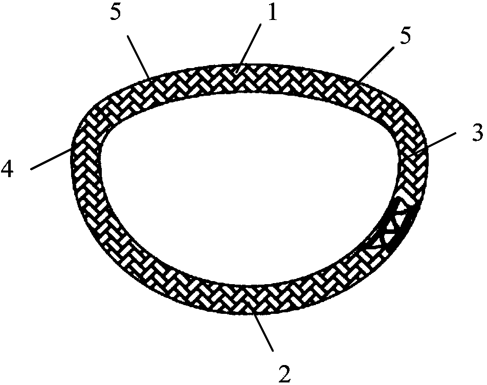
[0063] This embodiment provides an artificial mitral annulus forming ring. Such as figure 1 As shown, the mitral annuloplasty ring is a closed three-dimensional saddle-shaped structure, and its ring-shaped main body is composed of an anterior ring segment 1 , a rear ring segment 2 , a left ring segment 3 and a right ring segment 4 . The higher bow-shaped protrusion of the forming ring is the front ring segment 1, the lower protrusion is the rear ring segment 2, and the two concave segments are respectively the left ring segment 3 and the right ring segment 4, the front ring segment 1 and the left ring segment 3 Connecting segments 5 are arranged between adjacent ring segments in the right ring segment 4 and right ring segment 4 respectively.

[0064] Such as figure 2 As shown, the middle point of the rear ring segment 2 is used as the connection point, and the forming ring is developed into a straight tubular helical structure along the circumferential direction, the outer ...

Embodiment 2

[0071] This embodiment provides an artificial mitral annuloplasty ring, Figure 5 In order to expand the annular body of the forming ring into a straight tubular helical structure along the circumferential direction. Figure 6 to form Figure 5 Sheet strips in a tubular helical structure. Wherein the sheet material strip in this embodiment is processed by medical stainless steel plate, its width is larger than the sheet material strip in embodiment 1, and there are a plurality of elongated hollow structures on it. Besides, other shapes and structures of the artificial mitral annulus forming ring provided in this embodiment are the same as those of the artificial mitral annulus forming ring in Embodiment 1. The present invention achieves the purpose of further adjusting the rigidity of each ring segment through the setting of the hollow structure.

Embodiment 3

[0073] This embodiment provides an artificial mitral annuloplasty ring whose shape is as figure 1 As shown, it is the same shape as the artificial mitral annuloplasty ring in Example 1.

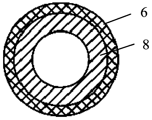
[0074] Such as Figure 7 As shown, the middle point of the rear ring segment 2 is the closed connection point, and the forming ring main body 8 is expanded into a straight tubular helical structure along the circumferential direction of the ring, and its outer diameter can be 1-3mm, and the pitch is consistent. The width of the plate strip forming the helical shape varies from place to place, and its thickness can generally be 0.1-0.6 mm, and it is formed by laser cutting or stamping and other methods. Figure 10 In order to roll the plate strips of the main structure, the main structure adopts the double plate strip method shown in the figure, and is rolled into a double helix structure, so as to increase the ability of the plate strips to resist fatigue. Such as Figure 10 As shown, the ...


PUM

PropertyMeasurementUnit
Outer diameteraaaaaaaaaa
Thicknessaaaaaaaaaa
Thicknessaaaaaaaaaa

Abstract

The invention provides an artificial heart valve annuloplastic ring. The artificial heart valve annuloplastic ring comprises an outer layer and an inner layer main body structure, wherein the outer layer covers the inner layer main body structure and is used for suturing heart tissues; the inner layer main body structure is provided with a tubular spiral structure formed by curling sheet materials, and the tubular spiral structure can adjust the rigidity of the annuloplastic ring. The artificial heart valve annuloplastic ring is simple in structure, easy to rigidity-adjust and convenient to manufacture and process.

Description

technical field [0001] The invention relates to an artificial heart valve forming ring, which belongs to the technical field of medical instruments. Background technique [0002] When the heart contracts, the heart's mitral and tricuspid valves close, allowing blood in the ventricles to flow into the arteries while preventing blood in the ventricles from flowing back into the atria. Dilation of the valve sinus, rupture of the subvalvular chordae, perforation of the valve leaflets, prolapse of the valve leaflets and other diseases make the valve leaflets unable to fully close when the ventricle contracts, causing blood to flow back into the atrium. Plastic ring implantation is an important means to reshape the diseased mitral and tricuspid valves clinically to maintain the normal shape and contour, and it can repair the closed and incomplete mitral and tricuspid valve leaflets caused by the disease. problems such as ventricular regurgitation. [0003] At present, there are ...

Claims


Application Information

Patent Timeline
IPC IPC(8): A61F2/24
CPCA61F2/2445A61F2/2448A61F2210/0076A61F2230/0091A61F2250/0015A61F2250/0018A61F2250/0029
Inventor 金昌钟生平
Owner KINGSTRONBIOCHANGSHU CO LTD
Learn More