Pm motor position-sensorless control device
A control device and sensor technology, applied in the direction of controlling electromechanical transmission devices, control systems, and generators, etc., can solve the problems of less magnetic saturation, inability to operate correctly, and inability to apply
- Summary
- Abstract
- Description
- Claims
- Application Information
AI Technical Summary
Problems solved by technology
Method used
Image

Examples
Embodiment 1
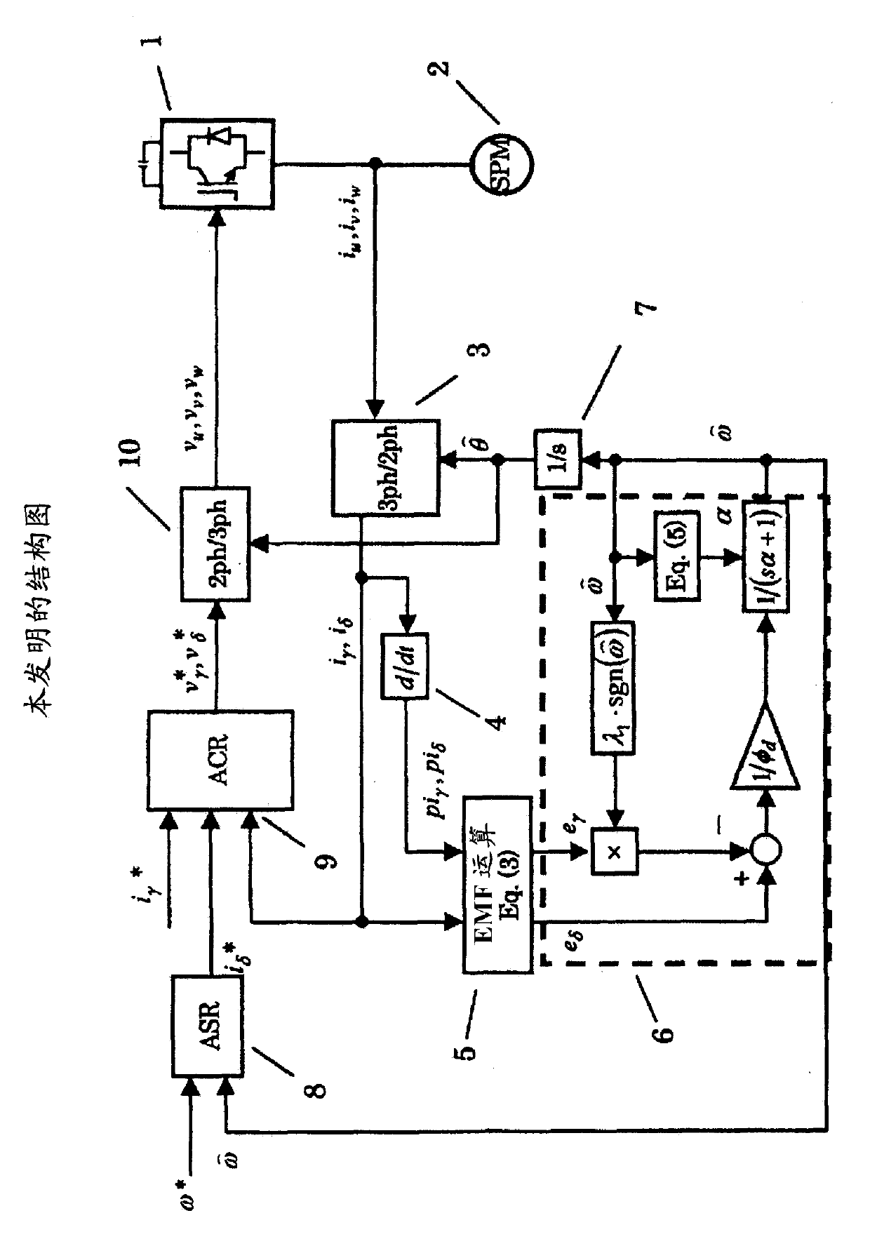
[0054] figure 1 A block diagram showing the position sensorless control device according to the first embodiment of the present invention is shown. 1 is the inverter controlled by PWM, and 2 is the PM motor. Here, the excitation axis of the N pole of the PM motor of the actual machine is defined as the d-axis, while the phase that advances 90° in the forward direction is defined as the q-axis. . However, since there is no position sensor, the d-axis and q-axis cannot be directly detected. Therefore, the N pole axis assumed by the magnetic pole estimation is defined as the γ axis, and the phase advancing 90 degrees in the rotation direction is defined as the δ axis.
[0055] 3 is a rotating coordinate conversion unit, which inputs the three-phase current i detected by the current sensor u i v i w And the coordinates are transformed to i as the estimated axis γ i δ . Current signal i after coordinate transformation γ i δ are input to the current differential detection...
Embodiment 2
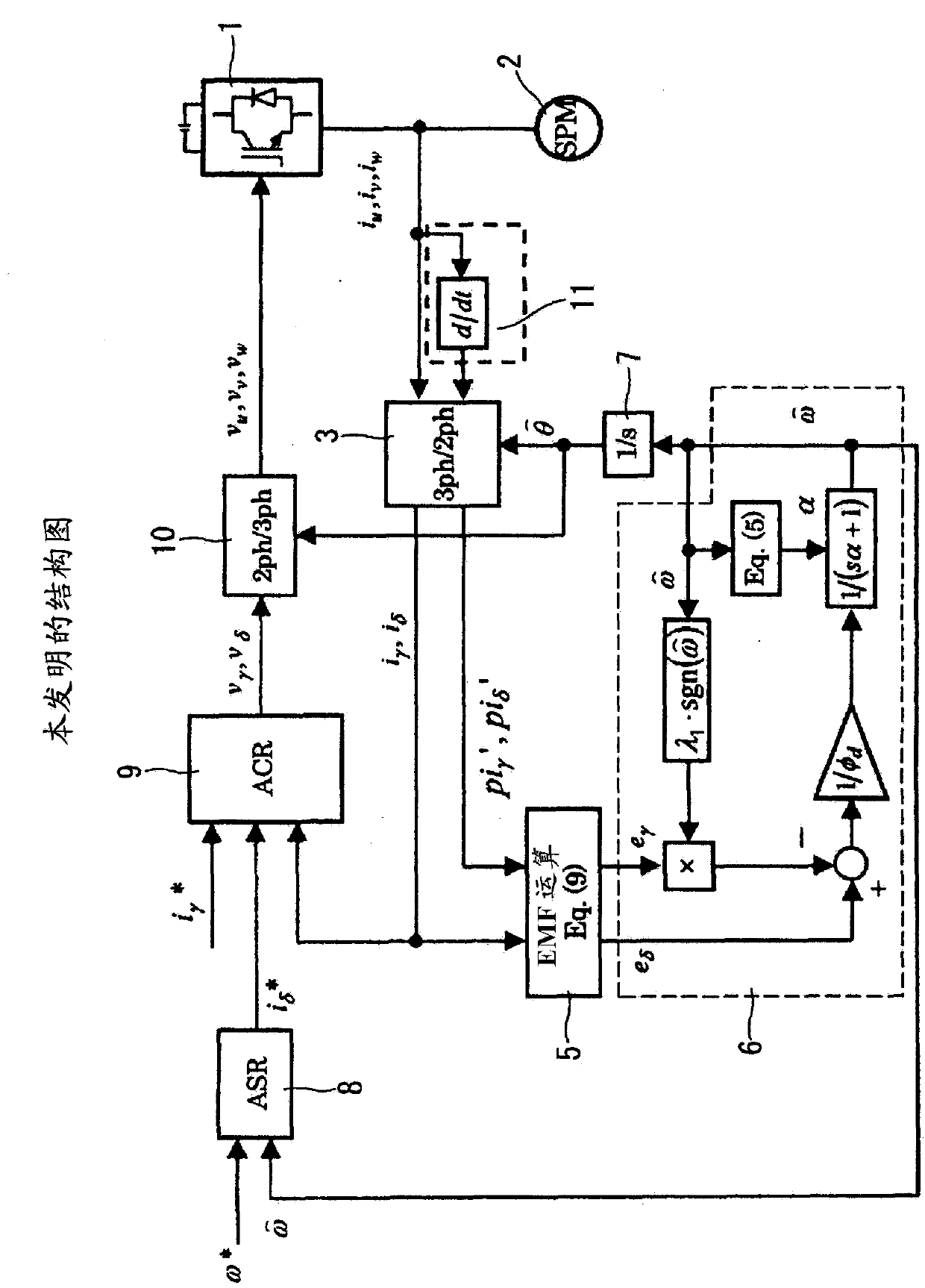
[0082] figure 2 represents a 2nd embodiment, with figure 1 The difference of the first embodiment shown is that the current differential information pi' is obtained by installing the current differential detection unit 11 in the fixed coordinate system. γ 、pi' δ .
[0083] In the first embodiment, in order to obtain the current differential information correctly, the estimated phase θ^ used in the rotational coordinate transformation must also be a value of the continuous system. Therefore, when the three-phase current signals are A / D-converted into digital values, the estimated phase θ^ used in the rotational coordinate conversion also needs to be updated sequentially, which increases the amount of computation. This embodiment 2 takes this point into consideration, by being configured to obtain the current differential information pi' in a fixed coordinate system γ 、pi' δ , it becomes unnecessary to update the estimated phase θ^ successively, and a simple calculation c...
Embodiment 3
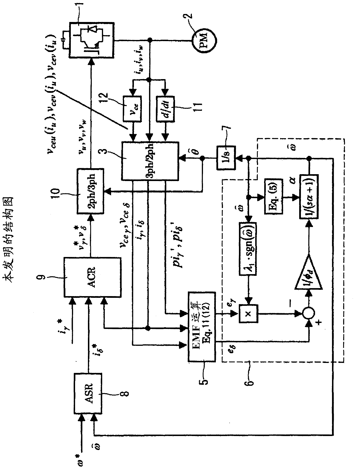
[0112]In Examples 1 and 2, the induced voltage was calculated using the current differential during the zero voltage vector period. Embodiments 1 and 2 are characterized in that they are not affected by dead time, operation delay of the switching element, etc., because the current change during the period in which the switching element used in the inverter is not operating is detected. However, when the switching elements are strictly implemented by semiconductor elements such as IGBTs and diodes to form an inverter, the inverter output voltage does not become zero during the zero-voltage vector period due to the voltage drop of each element. .
[0113] This embodiment considers this point and constitutes as image 3 as shown.
[0114] Generally, since the voltage drop component of the switching element has a relationship with the current, the voltage drop amount of the semiconductor element is estimated and corrected based on the detected value of the current component of e...
PUM
 Abstract
Description
Claims
Application Information
 - R&D
- Intellectual Property
- Life Sciences
- Materials
- Tech Scout
- Unparalleled Data Quality
- Higher Quality Content
- 60% Fewer Hallucinations
Browse by: Latest US Patents, China's latest patents, Technical Efficacy Thesaurus, Application Domain, Technology Topic, Popular Technical Reports.
© 2025 PatSnap. All rights reserved.Legal|Privacy policy|Modern Slavery Act Transparency Statement|Sitemap|About US| Contact US: help@patsnap.com