
Fin field effect transistor and manufacturing method thereof

A fin-type field effect and manufacturing method technology, applied in semiconductor/solid-state device manufacturing, semiconductor devices, electrical components, etc., can solve problems such as low electron mobility

Active Publication Date: 2016-12-21
SEMICON MFG INT (SHANGHAI) CORP
View PDF4 Cites 0 Cited by
  • Summary
  • Abstract
  • Description
  • Claims
  • Application Information

AI Technical Summary

Problems solved by technology

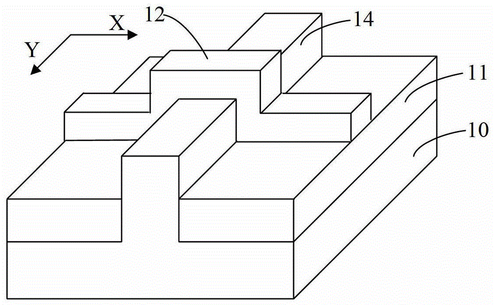
[0005] However, figure 1 The prior art FinFET shown has a low electron mobility
[0006] In the Chinese patent whose publication number is CN100521116C discloses a kind of fin field effect transistor, but does not solve above-mentioned technical problem

Method used


Image

  • Fin field effect transistor and manufacturing method thereof
  • Fin field effect transistor and manufacturing method thereof
  • Fin field effect transistor and manufacturing method thereof

Examples


Embodiment Construction

[0015] In the following description, numerous specific details are set forth in order to provide a thorough understanding of the present invention. However, the present invention can be implemented in many other ways different from those described here, and those skilled in the art can make similar extensions without violating the connotation of the present invention, so the present invention is not limited by the specific implementations disclosed below.

[0016] Secondly, the present invention is described in detail by means of schematic diagrams. When describing the embodiments of the present invention in detail, for convenience of explanation, the schematic diagrams are only examples, which should not limit the protection scope of the present invention.

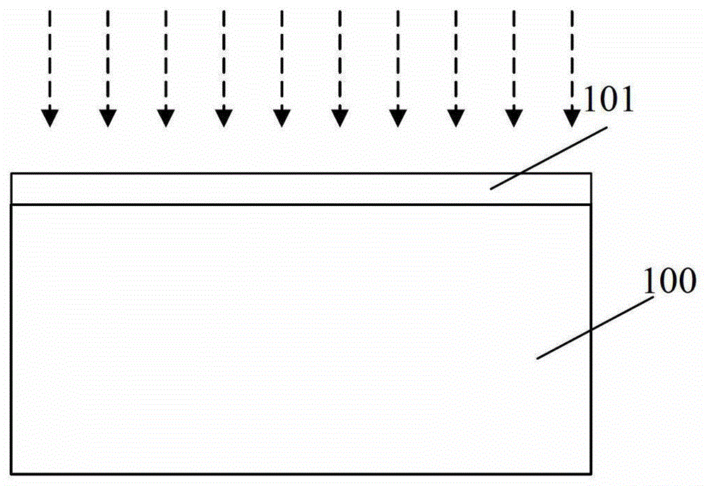
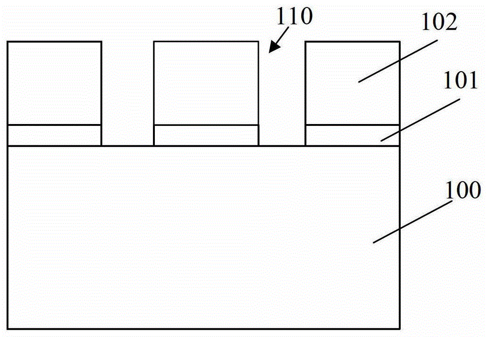
[0017] In order to solve the problems in the prior art, the present invention provides a method for manufacturing a fin field effect transistor. refer to Figure 2 to Figure 9 , shows a cross-sectional view of an embodim...


PUM


Abstract

The invention relates to a fin type field effect transistor and a manufacturing method thereof. The manufacturing method comprises the following steps: forming an insulation layer at a semiconductor substrate; carrying out graphic processing on the insulation layer to form a plurality of trenches exposed out of the semiconductor substrate; filling the trenches with first semiconductor materials to form first semi-conductor layers; carrying out anti-channel doping ion diffusion material doping on the first semi-conductor layers; carrying out channel doping on the first semi-conductor layers; filling the trenches with second semi-conductor materials to form second semi-conductor layers; removing the insulation layer and exposing fin including the first semi-conductor layers and the second semi-conductor layers; and forming gate structure on the fins. The fin type field effect transistor includes a plurality of arranged on the semiconductor substrate and gate structures formed on the fins; the fins include first semiconductor layers and the second semiconductor layers, wherein the first semiconductor layers are doped with channel doping ions and anti-channel doping ion diffusion materials and the second semi-conductor layers are non-doping semi-conductor layers. According to the invention, the electronic mobility can be improved.

Description

technical field [0001] The invention relates to the field of semiconductor manufacturing, in particular to a fin field effect transistor and a manufacturing method thereof. Background technique [0002] In order to keep up with the pace of Moore's Law, people have to continue to shrink the feature size of MOSFET transistors. Doing so can bring benefits such as increasing chip density and improving the switching speed of MOSFETs. As the channel length of the device is shortened, the distance between the drain and the source is also shortened, so that the control ability of the gate to the channel becomes worse, and it becomes more and more difficult for the gate voltage to pinch off the channel. The larger the , the more likely the so-called short-channel effects (SCE: short-channel effects) will occur. [0003] For this reason, planar CMOS transistors are gradually transitioning to a three-dimensional (3D) Fin Field Effect Transistor (Fin Field Effect Transistor, FinFET) d...

Claims


Application Information

Patent Timeline
Patent Type & Authority Patents(China)
IPC IPC(8): H01L21/336H01L29/78H01L29/06
CPCH01L29/1054H01L29/66795H01L29/7851
Inventor 赵猛
Owner SEMICON MFG INT (SHANGHAI) CORP
Learn More