
A Simulation Method of Digitized Angle Surface Target

A target simulation and angle surface technology, which is applied in the field of digital angle surface target simulation, can solve the problems of being easily affected by ambient temperature, difficult to achieve synchronization relationship, and large debugging workload, so as to solve the influence of temperature drift and achieve good temperature characteristics. , the effect of reducing hardware costs

Active Publication Date: 2017-02-15
NANJING CHANGFENG AEROSPACE ELECTRONICS SCI & TECH
View PDF6 Cites 0 Cited by
  • Summary
  • Abstract
  • Description
  • Claims
  • Application Information

AI Technical Summary

Problems solved by technology

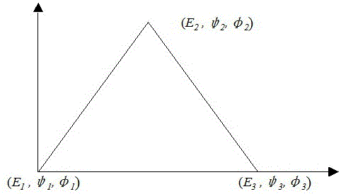
[0003] In the prior art, analog signals are often used for angle simulation, and the use of analog signals to achieve angular position control requires maintaining a strict phase relationship among the three channels A, B, and C of the triplet, which is easily affected by the ambient temperature. In addition, each triplet can only output a specific angle in the control of the antenna array. In order to achieve the target of the angle plane, multiple triplets need to be combined. This method has many disadvantages: ① In order to achieve complex goals, multiple Channels, for example, a target model with 10 scattering points requires 10 channels, which increases the cost; ②The synchronization relationship between multiple channels is difficult to achieve, and the adjustment workload for amplitude and phase balance is extremely huge

Method used


Image

  • A Simulation Method of Digitized Angle Surface Target
  • A Simulation Method of Digitized Angle Surface Target
  • A Simulation Method of Digitized Angle Surface Target

Examples


Embodiment 1

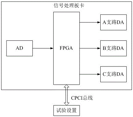
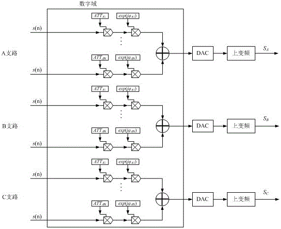
[0036] This embodiment relates to a method for simulating a digital angular surface target. The core for digital angular surface target simulation is a signal processing board for digital domain processing. Refer to figure 2 , the signal processing board includes a 3Gsps sampling rate AD chip, a Xilinx V5SX95T FPGA chip and three 3Gsps DA chips. The design performs angle modulation processing on the input digital signal, and the digital signals of A, B, and C branches after angle modulation are respectively sent to the corresponding DA chip for digital-to-analog conversion.

[0037] The specific steps of the above digitized angular surface target simulation method are as follows:

[0038] 1) The signal processing board obtains the angle information θ of the N scattering points of the surface target required for the current simulation, including the azimuth information and the high and low angle information, from the simulation setting computer through the standard CPCI bus i...

Embodiment 2

[0071] This embodiment relates to a method for simulating a digital angular surface target. The core for digital angular surface target simulation is a signal processing board for digital domain processing. Refer to figure 2 , the signal processing board includes a 3Gsps sampling rate AD chip, a Xilinx V5SX95T FPGA chip and three 3Gsps DA chips. The design performs angle modulation processing on the input digital signal, and the digital signals of A, B, and C branches after angle modulation are respectively sent to the corresponding DA chip for digital-to-analog conversion.

[0072] The specific steps of the above digitized angular surface target simulation method are as follows:

[0073] 1) The signal processing board obtains the angle information θ of the N scattering points of the surface target required for the current simulation, including the azimuth information and the high and low angle information, from the simulation setting computer through the standard CPCI bus i...


PUM


Abstract

The invention relates to a method for simulating a digitization angle area target. According to the method, an analog signal is converted into a digital signal, and angle information is debugged through the digitization method so that the simulation of the angle area target can be achieved. By means of the method, angle area target signals comprising a plurality of pieces of angle information can be output from the same channel, cost is reduced, the debugging workload is reduced, and the reliability of a system is improved.

Description

technical field [0001] The invention relates to a semi-physical simulation technology, in particular to a digital angle surface target simulation method. Background technique [0002] In the existing hardware-in-the-loop RF simulation technology, the angle simulation is usually realized by means of array antenna triplets. The three adjacent antennas on the array antenna form a triplet, and the signal of the test is simulated by the signal radiated by the triplet, and the radiation direction is facing the equipment under test. Movement of the radiated signal within a triplet, or from one triplet to another, represents movement in the angular position of the target. [0003] In the prior art, analog signals are often used for angle simulation, and the use of analog signals to achieve angular position control requires maintaining a strict phase relationship among the three channels A, B, and C of the triplet, which is easily affected by the ambient temperature. In addition, e...

Claims


Application Information

Patent Timeline
Patent Type & Authority Patents(China)
IPC IPC(8): G05B17/02
Inventor 江长勇朱健康
Owner NANJING CHANGFENG AEROSPACE ELECTRONICS SCI & TECH
Learn More