
Method and system for measuring humidity of high-temperature high-pressure high-humidity gas

A technology of high temperature, high pressure and gas temperature, applied in the direction of analyzing materials, instruments, etc., can solve the problem of uncertainty in the linearity of moisture-sensing components

Active Publication Date: 2014-04-09
STATE NUCLEAR HUAQING BEIJING NUCLEAR POWER TECH R & D CENT +1
View PDF4 Cites 13 Cited by
  • Summary
  • Abstract
  • Description
  • Claims
  • Application Information

AI Technical Summary

Problems solved by technology

At this time, it is obvious that the steam partial pressure has greatly exceeded 101.325kPa, and the linearity of the humidity sensing element is uncertain, so generally speaking, the humidity sensor technology has reached the temperature measurement range of -60°C~180°C, and the humidity measurement range is 0%RH~ 99%RH, accuracy up to 0.8%RH is inappropriate

Method used


Image

  • Method and system for measuring humidity of high-temperature high-pressure high-humidity gas
  • Method and system for measuring humidity of high-temperature high-pressure high-humidity gas
  • Method and system for measuring humidity of high-temperature high-pressure high-humidity gas

Examples


Embodiment 1

[0025] Example 1 (High temperature, high pressure and high humidity gas humidity measurement):

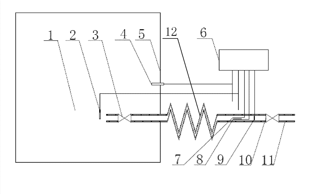
[0026] According to the attached figure 1 Arrange temperature, pressure and humidity measuring points. Among them, the temperature sensor 7 and the humidity sensor 8 may also be a temperature and humidity sensor. The temperature value of the heat-tracing insulation pipeline 11 is set to 110°C, and the pressure reduction value of the pressure reducing regulator 3 is set to an absolute pressure of 1.2 atm. The pressure reducing and stabilizing valve is preferably arranged at the inlet of the pipeline. The opening degree of the discharge device, which is preferably arranged at the end of the pipeline, is adjusted so that the gas is discharged at a smaller flow rate. The discharge device is preferably a needle valve 10. At this time, the partial pressure of the steam after pressure reduction e 1 =0.849 atm; temperature T 1 =108℃; pressure P 1 =1.21atm; the temperature T in the pressu...

Embodiment 2

[0039] Example 2 (Analysis of saturated and partially condensed gas):

[0040] Embodiment 2 is similar to Embodiment 1, and the same parts of the two will not be repeated. According to the attached figure 1 Arrange temperature, pressure and humidity measuring points. Among them, the temperature sensor 7 and the humidity sensor 8 may also be a temperature and humidity sensor. The temperature value of the heat-tracing insulation pipeline 11 is set to 120°C, and the pressure reduction value of the pressure reducing regulator 3 is set to an absolute pressure of 1.2 atm. Adjust the opening of the needle valve 10 to discharge the gas at a smaller flow rate. At this time, the partial pressure of the steam after pressure reduction e 1 =0.915 atm; temperature T 1 =120℃; pressure P 1 =1.20atm; temperature T in the pressure vessel 0 =140℃; pressure P 0 =6.0atm.

[0041] According to the measured parameters, the method steps to calculate the humidity and other parameters of the measured h...


PUM


Abstract

The invention relates to a method and a system for measuring humidity of high-temperature high-pressure high-humidity gas. Aiming at defects and deficiencies of gas humidity measuring methods and instruments at present, the objective and the task of the invention are to provide a novel method for measuring the humidity of the high-temperature high-pressure high-humidity gas comprising gas containing saturated vapor, namely a measuring method in which the humidity and related parameters of the original gas are obtained by a step of subjecting the high-temperature high-pressure gas to pressure-reducing pressure-stabilizing heat-insulating heating treatment, a step of detecting the vapor content in a low pressure and a step of calculating through temperature and pressure conversion. The invention also discloses the system for measuring the humidity of the high-temperature high-pressure high-humidity gas.

Description

Technical field [0001] The invention relates to the technical field of gas state parameter measurement, and more specifically, to a method for measuring the humidity of high-temperature, high-pressure and high-humidity gas. Background technique [0002] Humidity measurement is frequently used in human life and production activities. With the advancement of technology, humidity measurement has spread throughout the fields of industry, agriculture, national defense, and science and technology. Various humidity measuring instruments are widely used in petrochemical, microelectronics, communications, meteorology, electric power, environmental monitoring, pharmaceuticals, construction, air conditioning, military aerospace, tobacco, automobiles and other industries. [0003] Modern humidity measurement technologies are mainly concentrated in mechanical (hair type and polymer elastic element type), wet and dry bulb type (Assmann type and natural ventilation type) and humidity sensor typ...

Claims


Application Information

Patent Timeline
Patent Type & Authority Applications(China)
IPC IPC(8): G01N7/00
Inventor 王欢田芳常华健毛丛清安旭常磊
Owner STATE NUCLEAR HUAQING BEIJING NUCLEAR POWER TECH R & D CENT
Learn More