
Biphase multi-shaft drive system

A technology of multi-axis transmission and intermediate shaft, applied in the direction of transmission chain, transmission device, belt/chain/gear, etc., can solve the problems of high rigid shock and vibration, vibration of chain transmission system, low fatigue life, etc., to reduce shock and Vibration, improved fatigue life, improved overall performance

Inactive Publication Date: 2014-03-12
JILIN UNIV
View PDF5 Cites 3 Cited by
  • Summary
  • Abstract
  • Description
  • Claims
  • Application Information

AI Technical Summary

Problems solved by technology

[0004] In the toothed chain transmission system in the prior art, when the chain plate and the sprocket mesh, the contact between the chain plate and the sprocket is actually a line contact, there is a rigid impact between the chain plate and the sprocket, and the vibration of the chain transmission system is relatively large. severe, noisy
In addition, the transmission sprocket is single-row, the greater the power transmitted by the single-row sprocket, the more chain rows are required, the longer the pin shaft is, the more serious the deformation of the pin shaft is, and the overall performance of the transmission system is poor.
[0005] The existing Chinese patent (publication number: CN201110356Y) discloses a toothed chain transmission system, but what it describes is a round pin toothed chain transmission system, which uses a single row of sprockets, chain plates and chains During the meshing process of the wheels, the rigid shock and vibration are relatively large, and the noise is large. The meshing point gradually moves during the contact process, which belongs to sliding friction, and the wear is serious, and the fatigue life is not high

Method used


Image

  • Biphase multi-shaft drive system
  • Biphase multi-shaft drive system
  • Biphase multi-shaft drive system

Examples


Embodiment Construction

[0037] The present invention will be further described below in conjunction with the embodiments shown in the accompanying drawings.

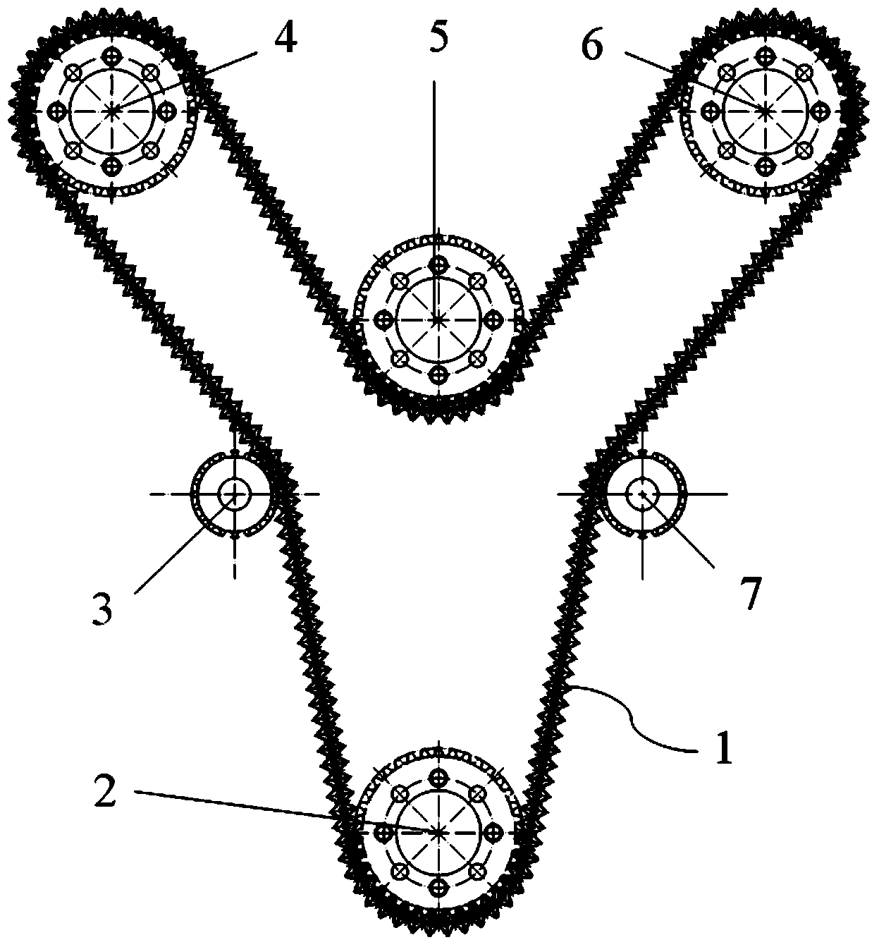
[0038] figure 1 It is the overall assembly drawing of the present invention, and it can be seen that a kind of dual-phase multi-axis transmission system of the present invention consists of Hy-Vo toothed chain 1, driving sprocket 2, tensioning sprocket A 3, driven sprocket B 4 and the middle Shaft sprocket 5, driven sprocket C 6 and tensioning sprocket D 7 form. The Hy-Vo toothed chain 1 meshes with the driving sprocket 2, the tensioning sprocket A 3, the driven sprocket B 4 and the intermediate shaft sprocket 5, the driven sprocket C 6 and the tensioning sprocket D 7 transmission;

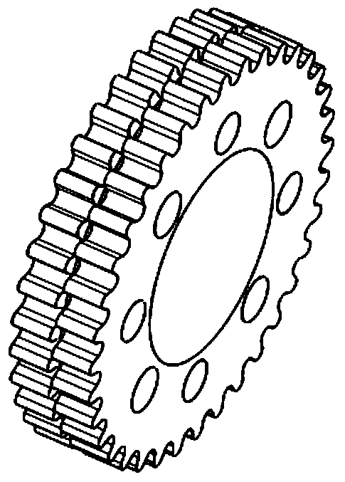
[0039] Referring to Figure 3(a)-Figure 3(c), it can be seen that the driving sprocket 2, tensioning sprocket A 3, driven sprocket B 4, intermediate shaft sprocket 5, driven sprocket C 6 and tension sprocket Tight sprocket wheels 7 are two-phase sprocket wheels, ...


PUM


Abstract

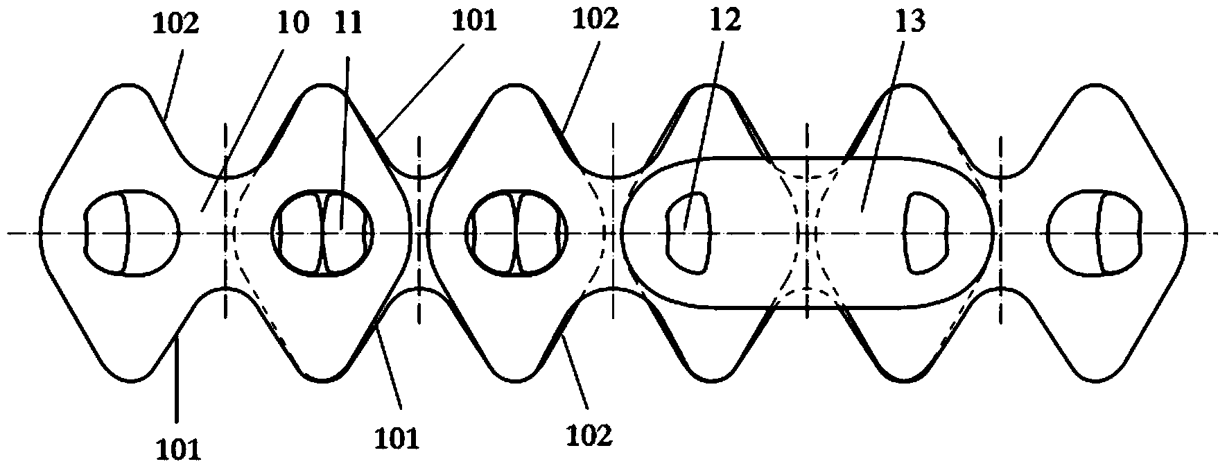
The invention discloses a biphase multi-shaft drive system. The biphase multi-shaft drive system consists of an H(y)-V(o) tooth-shaped chain, a driving chain wheel, a tightening chain wheel A, a driven chain wheel B, an intermediate shaft chain wheel, a driven chain wheel C and a tightening chain wheel D, wherein the H(y)-V(o) tooth-shaped chain is meshed with the driving chain wheel, the tightening chain wheel A, the driven chain wheel B, the intermediate shaft chain wheel, the driven chain wheel C and the tightening chain wheel D in a drive mode; all the chain wheels are biphase chain wheels, that is, all the chain wheels consist of two rows of chain wheels, and the two rows of chain wheels are different by half tooth-shaped angles. According to the invention, the biphase chain wheels which are different by half tooth-shaped angles replace the traditional single-row chain wheels; chain plates of three kinds of different meshed mechanisms are ranked sequentially, the meshing noise can be reduced by adjusting the meshing rhythm and frequency, and the biphase multi-shaft drive system also can be applied to the working conditions of heavy load and variable load; and heart-shaped contact wires of pin shafts replace the traditional circular arc wires, so that the slide friction among the pin shafts is converted into rolling friction, and the fatigue service lives of chains are prolonged.

Description

technical field [0001] The invention belongs to the technical field of mechanical transmission, and in particular relates to a two-phase multi-shaft transmission system with relatively low vibration and noise. Background technique [0002] The transmission system is to combine several mechanisms according to the expected needs to form a mechanical transmission system, which can realize the change of speed and the transformation of motion form, so that the actuator can complete the predetermined motion, and at the same time transmit the required power and torque to achieve the expected movement and power transmission. [0003] In recent years, the chain has been widely used in mechanical transmission systems, especially under the conditions of high speed, heavy load, low noise and large center distance, its transmission performance is better than that of belt transmission and gear transmission, and has become the first choice of many industries One of the transmission forms....

Claims


Application Information

Patent Timeline
Patent Type & Authority Applications(China)
IPC IPC(8): F16H7/06F16H7/08F16G13/04
CPCF16H7/06F16G13/04F16H7/08
Inventor 程亚兵郭海涛王洋殷帅兵安立持万嫩李磊
Owner JILIN UNIV
Learn More