
Split-type axial connecting device

A technology of axial connection and detachment, which is applied in the direction of couplings, rigid shaft couplings, and clutches that mesh with each other. It can solve the problems of coaxiality decline, waste of energy, and poor stability, and achieve improved stability. , improve the rationality and reduce the effect of rotational resistance

Active Publication Date: 2018-11-13
义乌市鼎莎针织有限公司
View PDF5 Cites 6 Cited by
  • Summary
  • Abstract
  • Description
  • Claims
  • Application Information

AI Technical Summary

Problems solved by technology

[0005] Aiming at the deficiencies of the prior art, the present invention provides a detachable axial connection device, which can selectively control a certain transmission shaft for transmission, with small power loss, better effect of step-by-step connection transmission, and improved transmission of the transmission shaft. The advantages of coaxiality of rotation and better stability solve the problem that most of the joints of the existing transmission shafts are fixed connections, so that a larger power source needs to be provided during the transmission, and the longer the transmission shaft will make the transmission The worse the effect and stability, the lower the coaxiality of the transmission shaft rotation will be, and the greater the transmission loss will be. In some processing processes, the processing modules are connected and work through the transmission shaft. Sometimes It is only necessary to perform a single processing procedure on the product, but since multiple processing modules are connected through the transmission shaft, it is bound to start the work of multiple processing modules at the same time due to a certain processing procedure, which is a waste of energy.

Method used


Image

  • Split-type axial connecting device
  • Split-type axial connecting device
  • Split-type axial connecting device

Examples


Embodiment Construction

[0028] The following will clearly and completely describe the technical solutions in the embodiments of the present invention with reference to the accompanying drawings in the embodiments of the present invention. Obviously, the described embodiments are only some, not all, embodiments of the present invention. Based on the embodiments of the present invention, all other embodiments obtained by persons of ordinary skill in the art without making creative efforts belong to the protection scope of the present invention.

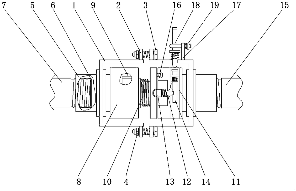
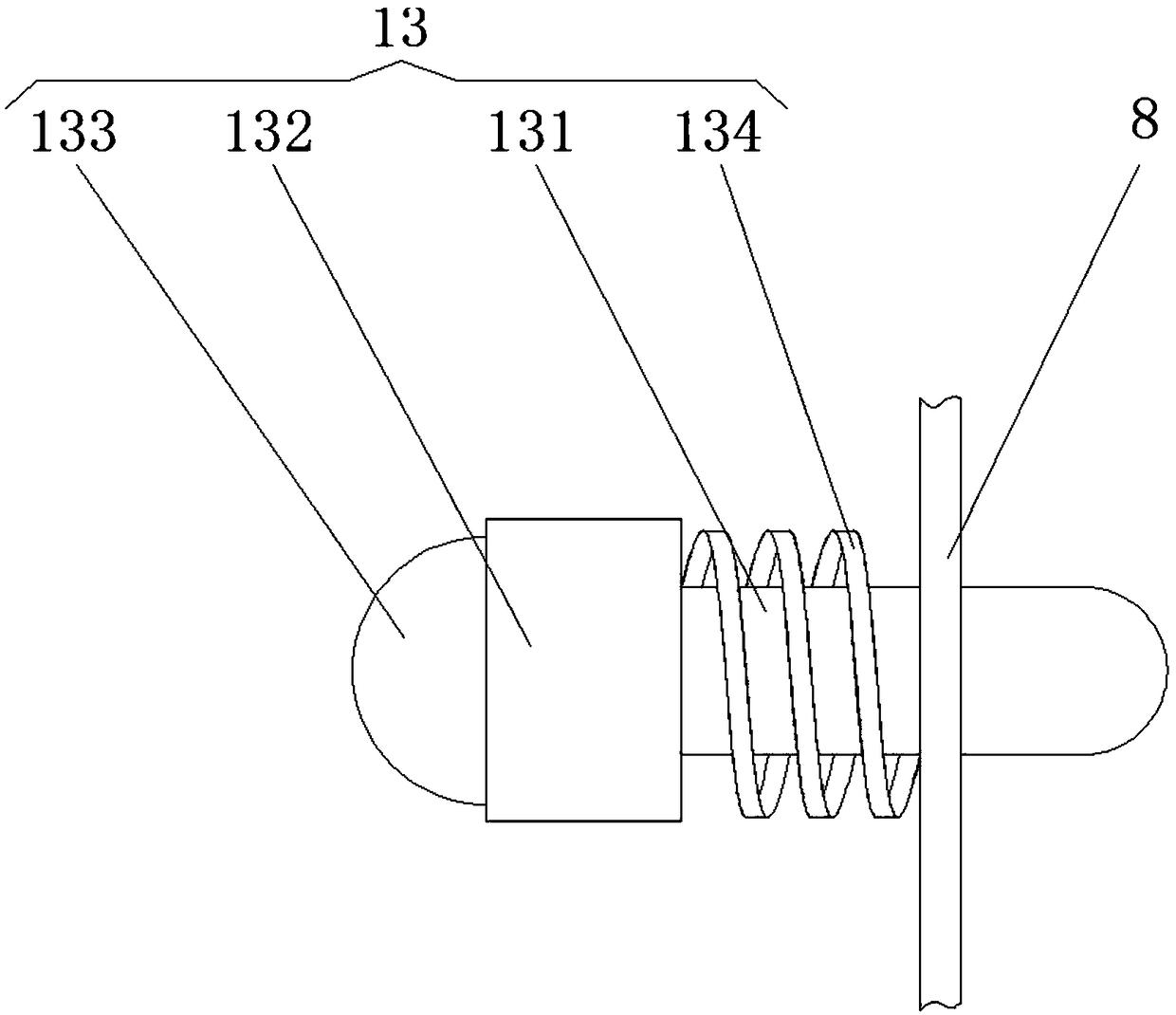
[0029] see Figure 1-5, a detachable axial connection device, including two sets of couplings 1, fixed steel plates 2 are fixedly installed on both sides of the couplings 1, and the fixed steel plates 2 on the two sets of couplings 1 are fastened by fastening bolts 3 It is threadedly connected with the lock nut 4, and the outer sides of the two sets of couplings 1 are connected to the connecting sleeve 5 through the bearing rotation. The end of the connecting ...


PUM


Abstract

The invention relates to the technical field of transmission shaft connecting devices, and discloses a split-type axial connecting device. The split-type axial connecting device comprises two sets ofcouplings, wherein fixed steel plates are fixedly installed on the two sides of each coupling, the fixed steel plates on one coupling are in threaded connection with the fixed steel plates on the other coupling through fastening bolts and locking nuts; a connecting shaft sleeve is rotationally connected to the outer side of each coupling through a bearing, an internal threaded hole is formed in the end, located outside the corresponding coupling, of each connecting shaft sleeve, and a first connecting shaft is in threaded connection with each coupling through the corresponding internal threaded hole. According to the split-type axial connecting device, separation and reunion of two connecting parts are controlled through clamping connection and separation of locating pins and pin holes, sothat rotation of the first connecting shaft is conveyed to the second connecting shaft through connection of the two connecting parts, and multi-shaft transmission is achieved. Meanwhile, when the two connecting parts are separated, rotation of the first connecting shaft is conveyed to the connecting device, that is to say, transmission is stopped, so that the split-shaft transmission effect is achieved, and the transmission stability is improved.

Description

technical field [0001] The invention relates to the technical field of transmission shaft connection equipment, in particular to a detachable axial connection device. Background technique [0002] The transmission shaft is a rotating body with high speed and few bearings, so its dynamic balance is very important. Generally, the transmission shaft must undergo a dynamic balance test before leaving the factory and be adjusted on a balancing machine. For a car with a front-engine rear-wheel drive, it is the shaft that transmits the rotation of the transmission to the final drive. It can be several sections, and the sections can be connected by universal joints. [0003] Transmission shafts are widely used in the field of mechanical processing. Nowadays, most mechanical equipment requires multi-section shafts for transmission to improve processing efficiency, and the connections of these transmission shafts are mostly fixed connections, which makes it necessary to provide The ...

Claims


Application Information

Patent Timeline
Patent Type & Authority Applications(China)
IPC IPC(8): F16D1/033F16D11/14
CPCF16D1/033F16D11/14F16D2011/006
Inventor 不公告发明人
Owner 义乌市鼎莎针织有限公司
Learn More