
Scroll drive type multi-axle drive mechanism

A multi-axis transmission and transmission technology, which is applied in transmission devices, gear transmission devices, mechanical equipment, etc., can solve the problems of large structure and difficult realization of adjustment mechanism.

Inactive Publication Date: 2007-12-19
JILIN UNIV
View PDF0 Cites 13 Cited by
  • Summary
  • Abstract
  • Description
  • Claims
  • Application Information

AI Technical Summary

Problems solved by technology

The shape adjustment of the basic body group of the multi-point forming device needs to adjust tens, hundreds or even thousands of axes. Difficult to achieve with space constraints

Method used


Image

  • Scroll drive type multi-axle drive mechanism
  • Scroll drive type multi-axle drive mechanism
  • Scroll drive type multi-axle drive mechanism

Examples


Embodiment Construction

[0032] The specific content and working process of the present invention will be further described below in conjunction with the embodiments shown in the accompanying drawings.

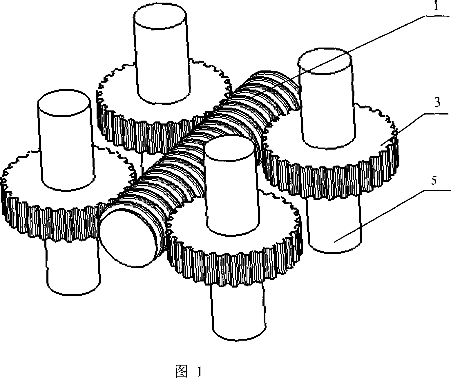
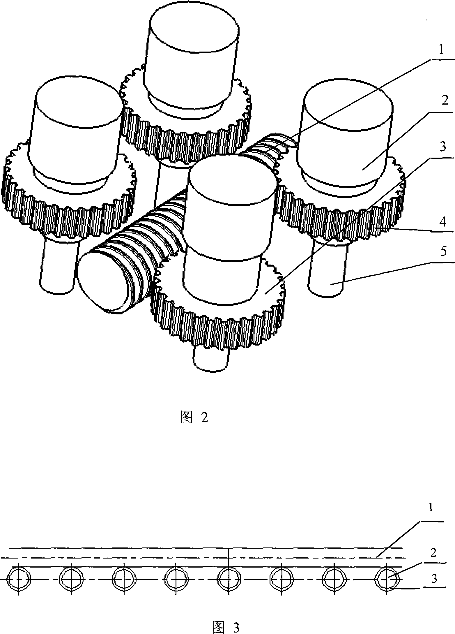
[0033] Refer to Figure 1: The worm drive type multi-axis transmission mechanism consists of one or more worms 1; one worm is arranged with a row of multiple worm gears or multiple rows of multiple worm gears, and one worm simultaneously meshes with multiple worm gears to achieve multi-axis transmission; changing the worm The direction of rotation can change the direction of rotation of the output shaft 5 . The worm 1 in the figure is an active input shaft, which can rotate in both positive and negative directions; it drives two rows (4) of worm gears. These worm gears are independent of each other and can rotate freely. The direction of rotation of the worm gear is controlled by the direction of rotation of the worm.

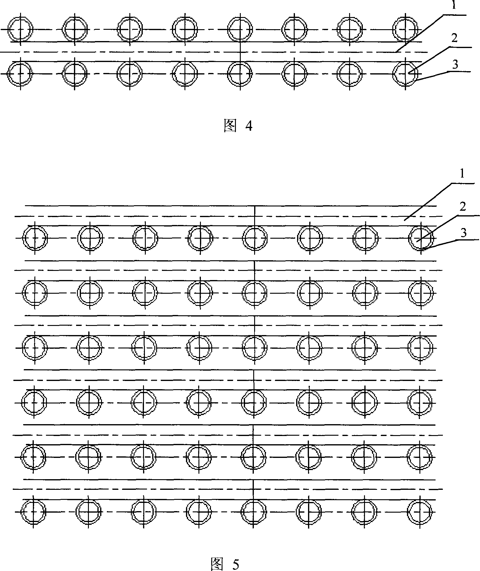
[0034] Refer to Fig. 2: The worm drive type multi-axis transmission mechanism is co...


PUM


Abstract

The present invention relates to a kind of worm-geared multishaft drive mechanism, it can be used in multishaft driven machine equipment, belonging to the field of mechanical engineering. Said mechanism includes the following several portions: worm, clutch, worm gears and output shaft. Said invention also provides the concrete structure of above-mentioned every portion, and also provides the working principle of said worm-geared multishaft drive mechanism and its concrete operation method.

Description

technical field [0001] The invention relates to a worm drive type multi-shaft transmission mechanism, which is mechanical equipment for multi-shaft transmission and belongs to the field of mechanical engineering. Background technique [0002] Mechanical transmission mechanisms usually use one shaft input and one shaft output. In order to improve work efficiency and reduce costs, one-axis input and multiple-axis output are often required. The shape adjustment of the basic body group of the multi-point forming device needs to adjust tens, hundreds or even thousands of axes. Space constraints are difficult to achieve. Contents of the invention [0003] The purpose of the present invention is to change the deficiency of the traditional transmission mechanism with one shaft input and one shaft output, and provide a worm drive type multi-shaft transmission mechanism. [0004] The above-mentioned purpose of the present invention is achieved in this way, and is described as fol...

Claims


Application Information

Patent Timeline
IPC IPC(8): F16H1/20F16H1/16
Inventor 李明哲付文智邓玉山崔相吉隋振刘纯国蔡中义孙刚李湘吉阎雪萍
Owner JILIN UNIV
Learn More