
Biomass gas burner

A biomass gas and burner technology, applied in burners, gas fuel burners, combustion methods, etc., can solve problems such as environmental pollution, tar clogging burners, and difficulty in cleaning

Active Publication Date: 2013-12-11
ZHEJIANG TUFF BOILER
View PDF5 Cites 4 Cited by
  • Summary
  • Abstract
  • Description
  • Claims
  • Application Information

AI Technical Summary

Problems solved by technology

[0003] Due to the characteristics of biomass gas itself, it is not easy to ignite biomass gas directly with electric sparks. At present, general biomass gas burners are ignited by liquefied petroleum gas or natural gas ignition guns, and a certain amount of liquefied petroleum gas is consumed every time the burner is started. or natural gas, and a series of safety procedures such as valve leak detection are required before each start-up, which is time-consuming and labor-intensive, and the economic benefits are not good
In addition, due to the generally high tar content of biomass gas, it cannot be fully cracked, and the combustion in the existing burner is insufficient, resulting in reduced combustion efficiency and easy to cause environmental pollution; at the same time, the resistance of the burner channel is slightly larger, which will cause tar. Builds up quickly, tends to cause tar to clog burners, and is very difficult to clean

Method used


Image

  • Biomass gas burner
  • Biomass gas burner
  • Biomass gas burner

Examples


Embodiment Construction

[0019] The specific implementation manners of the present invention will be further described in detail below in conjunction with the accompanying drawings.

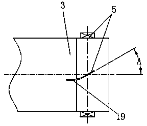
[0020] Such as Figure 1~3 As shown, the present invention includes the pilot gas passage 100 positioned at the axis, the pilot air passage 200 placed outside the pilot gas passage 100, the main combustion gas passage 300 placed outside the pilot air passage and the main combustion gas passage 300 of its outer layer. The fuel air channel 400, in this embodiment, the eternal fire gas channel 100 is the first pipe 1 arranged on the axis, the second pipe 2, the third pipe 3 and the shell 4 are coaxially sleeved outside the first pipe 1 in sequence, An open flame air passage 200 is formed between the first pipe 1 and the second pipe 2 , a main combustion gas passage 300 is formed between the second pipe 2 and the third pipe 3 , and a main combustion air passage is formed between the third pipe 3 and the casing 4 400. The p...


PUM


Abstract

The invention relates to a biomass gas burner. The biomass gas burner is characterized in that a long burning fire fuel gas channel, a long burning fire air channel, a main burning fuel gas channel and a main burning air channel are included; an ignition device penetrates through the long burning fire air channel and extends to the front end of the long burning fire fuel gas channel; the front portion of the long burning fire air channel, the front portion of the main burning fuel gas channel and the front portion of the main burning air channel are respectively provided with a whirlcone; the long burning fire air channel and the main burning air channel are respectively provided with a flow regulation device. According to the biomass gas burner, the long burning fire fuel gas channel and the long burning fire air channel are arranged so that a long burning fire standby function can be achieved, the consumption of liquefied gas or the consumption of natural gas is lowered, ignition burning waste is avoided, and boiler starting time is shortened; mixing of the air and biomass gas is reasonably controlled, the biomass gas can be made to be fully reacted with oxygen in a boiler, tar is burnt up, burning efficiency is improved, the tar can be prevented from being coked in the burner and the boiler, cleaning workloads are reduced, and meanwhile pollution to the environment can be reduced.

Description

technical field [0001] The invention relates to a burner, in particular to a biomass gas burner for burning biomass gas. Background technique [0002] As the fourth largest energy source in the world, biomass energy accounts for about 14% of the total global energy consumption. Biomass energy has a wide range of sources, high volatile content, low ash content, and low sulfur content. Due to the growth environment absorbing CO 2 The amount is equivalent to the CO emitted by combustion 2 amount, so CO is realized in the energy conversion process 2 The net emission is close to zero, which is conducive to improving the greenhouse effect. It is of great significance to research and develop technologies for efficient utilization of biomass energy, to save conventional fossil energy, and to optimize the energy structure. Biomass gas is a combustible gas produced by gasification furnaces of crop straw and forestry waste. It is a way for the development of biomass energy to la...

Claims


Application Information

Patent Timeline
Patent Type & Authority Applications(China)
IPC IPC(8): F23D14/24F23D14/46
Inventor 邵福南徐鹤殷鸿斌
Owner ZHEJIANG TUFF BOILER
Learn More