
motor control unit

A technology of motor control and magnetic flux controller, applied in motor generator control, AC motor control, control of electromechanical transmission devices, etc. High-speed threading, suppression of sudden change in excitation current, and improvement of characteristic deterioration

Active Publication Date: 2016-12-28
SANYO DENKI CO LTD
View PDF7 Cites 0 Cited by
  • Summary
  • Abstract
  • Description
  • Claims
  • Application Information

AI Technical Summary

Problems solved by technology

[0022] However, in order to achieve a high-speed response of the magnetic flux, the d-axis current changes greatly, and the total value of the d-axis current and the q-axis current exceeds the allowable current value of the inverter, and there is a problem of overcurrent

Method used


Image

  • motor control unit
  • motor control unit
  • motor control unit

Examples


Embodiment approach 1

[0066] [Structure of Motor Control Unit]

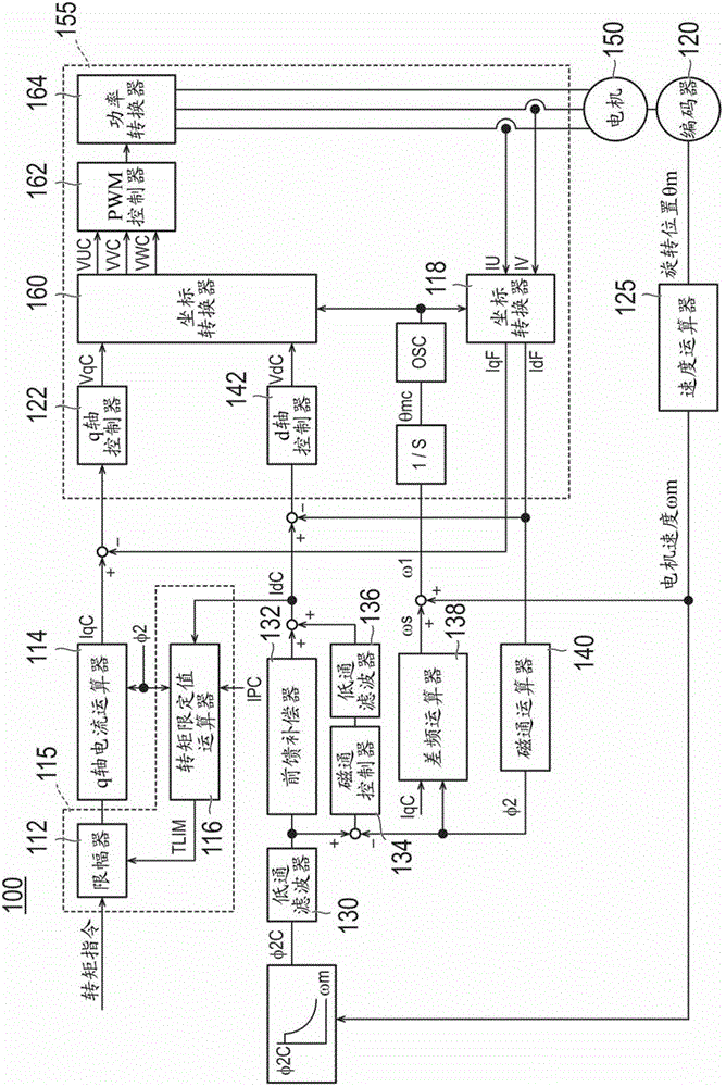
[0067] figure 1 It is a block diagram of the motor control device 100 of Embodiment 1.

[0068] As a system for providing the q-axis voltage command VqC, the motor control device 100 has a limiter 112, a q-axis current calculator 114, a torque limit value calculator 116, a coordinate converter 118, an encoder 120, a q-axis controller 122 and Speed ​​calculator 125. In addition, a torque command limiting unit 115 is constituted by a limiter 112 and a torque limit value calculator 116 .

[0069] The limiter 112 limits the received torque command using the torque limit value TLIM calculated by the torque limit value calculator 116 .

[0070] The q-axis current calculator 114 is used to output the q-axis current command IqC, which is obtained from the torque command output by the limiter 112 and the magnetic flux φ2 output by the magnetic flux calculator 140 .

[0071] Torque limit calculator 116 calculates torque limit TLIM received...

Embodiment approach 2

[0118] [Structure of Motor Control Unit]

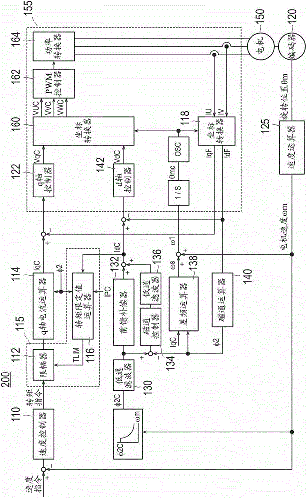
[0119] figure 2 It is a block diagram of the motor control device 200 of Embodiment 2. right figure 2 in and figure 1 The same constituent elements, labeled with figure 1 The same reference numerals.

[0120] The motor control device 200 differs from the motor control device 100 of the first embodiment in that only the speed controller 110 is provided as a system for providing the q-axis voltage command VqC.

[0121] The speed controller 110 subtracts the speed feedback from the speed calculator 125 from the received speed command, and outputs a torque command from the subtracted speed command.

[0122] The limiter 112 limits the torque command output from the speed controller 110 using the torque limit value TLIM calculated by the torque limit value calculator 116 .

[0123] The functions of the q-axis current calculator 114 , the torque limit value calculator 116 , the coordinate converter 118 , the encoder 120 , the q-axi...


PUM


Abstract

PROBLEM TO BE SOLVED: To perform acceleration / deceleration of a motor speed at a high speed by vector control.SOLUTION: A motor control apparatus includes: a torque command restriction unit 115 that restricts the magnitude of a given torque command so as to be in a predetermined magnitude range; a q-axis current calculator 114 that outputs a q-current command IqC based on the torque command of which the magnitude is restricted by the torque command restriction part 115; a magnetic flux control unit 134 that outputs a magnetic flux command by using a magnetic flux generated from the current flowing in the motor 150 and a secondary magnetic flux command outputted in the magnitude depending on a rotation speed of the motor 150; and a motor driving unit 155 that drives the motor 150 by the q-current command IqC outputted by the q-axis current calculator 114 and a d-axis current command IdC obtained by the magnetic flux control unit 134.

Description

technical field [0001] The invention relates to a motor control device capable of high-speed speed regulation of a motor through vector control. Background technique [0002] Since the spindle of a machine tool for thread processing needs to improve processing accuracy and shorten processing time, a spindle motor with low inertia and high-speed rotation is required. [0003] The spindle motor generally utilizes a synchronous machine or an induction motor. Especially when machine tool cost is given priority, induction motors that do not use rare earths are often used. [0004] With regard to conventional induction motors, the inertia is increased, and the operation stability due to the inertia is emphasized. In order to use an induction motor for thread processing that requires high-speed speed control, it is necessary to use a low-inertia induction motor, so it is necessary to improve the stability of the operation through the control system. [0005] Therefore, the high-...

Claims


Application Information

Patent Timeline
Patent Type & Authority Patents(China)
IPC IPC(8): H02P21/00H02P27/04H02P21/22H02P21/36H02P23/07H02P23/16H02P27/08
CPCH02P21/14
Inventor 井出勇治山崎悟史
Owner SANYO DENKI CO LTD
Learn More