Gate drive circuit, gate drive system and display panel

A gate drive circuit and gate drive technology, applied in the field of display screens, can solve the problem of deterioration of transistor characteristics of the gate drive unit in the last row, and achieve the effect of improving the deterioration of transistor characteristics

Active Publication Date: 2021-08-27
HEFEI BOE OPTOELECTRONICS TECH +1
View PDF14 Cites 0 Cited by
  • Summary
  • Abstract
  • Description
  • Claims
  • Application Information

AI Technical Summary

Problems solved by technology

Therefore, the first purpose of the present invention is to propose a gate drive circuit, which can make the scan signal entering the gate drive unit not only have the trigger function of the first line at the beginning of the frame, but also have the pull-up node output at the end of the frame. Noise function, which improves the deterioration of the transistor characteristics of the gate drive unit of the last row caused by the pull-up node of the last row being set high in the blank area for a long time in the existing gate drive unit design

Method used


Image

  • Gate drive circuit, gate drive system and display panel
  • Gate drive circuit, gate drive system and display panel
  • Gate drive circuit, gate drive system and display panel

Examples


Embodiment Construction

[0031]Embodiments of the present invention are described in detail below, examples of which are shown in the drawings, wherein the same or similar reference numerals designate the same or similar elements or elements having the same or similar functions throughout. The embodiments described below by referring to the figures are exemplary and are intended to explain the present invention and should not be construed as limiting the present invention.

[0032] The gate driving circuit, the gate driving system and the display panel proposed by the embodiments of the present invention are described below with reference to the accompanying drawings.

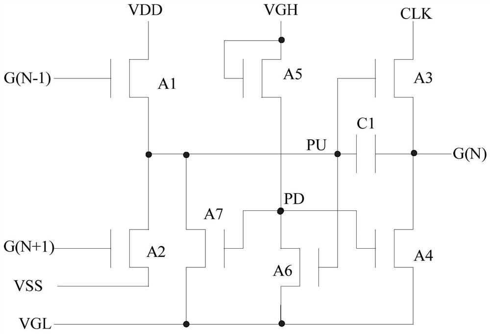
[0033] Figure 4 is a schematic diagram of a gate drive circuit according to an embodiment of the present invention. Such as Figure 4 As shown, the gate driving circuit 100 includes: a first input terminal STV_1 , a second input terminal STV_2 , a generating module 10 , and a signal output terminal STV_IN.

[0034] Wherein, the fir...


PUM


Abstract

The invention discloses a gate drive circuit, a gate drive system and a display panel. The circuit comprises: a first input terminal and a second input terminal for inputting a first single pulse vertical synchronous signal and a second single pulse respectively Vertical synchronous signal; generating module, is used for generating multi-pulse vertical synchronous signal, and multi-pulse vertical synchronous signal is high level in the first setting time of the beginning moment of each blank area, the second setting time of ending moment is High level; the signal output terminal is used to output the multi-pulse vertical synchronization signal to the input signal terminal of the gate driving unit of the first row and the reset signal terminal of the gate driving unit of the last row respectively. This circuit can make the scanning signal entering the gate drive unit not only have the trigger function of the first row at the beginning of the frame, but also have the function of releasing noise from the pull-up node at the end of the frame, which improves the design of the existing gate drive unit. The problem of deterioration of the transistor characteristics of the gate drive unit of the last row caused by setting the blank area high for a long time.

Description

technical field [0001] The invention relates to the technical field of display screens, in particular to a pixel circuit, a display panel and a display. Background technique [0002] GOA (Gate on Array) technology refers to integrating the gate driver (Gate Driver) of TFT-LCD on the array substrate to form a scanning drive for the panel. Due to its incomparable advantages in narrow frame application and cost, it has been widely used in Mobile (mobile phone) and NB (NoteBook, notebook) products. [0003] Currently, the general use of figure 1 In the gate drive circuit shown, A1 is the input TFT (input-TFT), which is used to charge the pull-up node PU; A3 is the pull-up TFT (Pull up-TFT), which is used to charge the GOA output terminal G (N ) for charging; A4 and A7 are pull-down TFTs (Pull down-TFT), used to discharge the pull-up nodes PU and G(N). A1-A7 are TFT (ThinFilm Transistor, thin film transistor), and PD is a pull-down node. The signal timing diagram of the gate ...

Claims


Application Information

Patent Timeline
Patent Type & Authority Patents(China)
IPC IPC(8): G09G3/36
CPCG09G3/3677
Inventor 章祯余超智吴芳芳唐如稳侯永康
Owner HEFEI BOE OPTOELECTRONICS TECH
Why Eureka
Try Eureka