Baffling fin casting plate-type air pre-heater

An air preheater and plate-type technology, which is applied in the field of high-efficiency heat exchange and energy-saving heat exchange equipment, can solve the problems of reducing heat exchange efficiency, unfavorable heat exchange, and increasing thermal resistance, so as to achieve good heat transfer effect and improve heat transfer film coefficient, the effect of increasing heat transfer efficiency

Active Publication Date: 2013-10-16
THE CHALLENGE PETROCHEM MACHINERY CORP
View PDF6 Cites 4 Cited by
  • Summary
  • Abstract
  • Description
  • Claims
  • Application Information

AI Technical Summary

Problems solved by technology

[0005] like figure 2 As shown, the cast finned plate heat exchange unit of the cast plate type air preheater in the above prior art, the fins are arranged in a short fin-like structure perpendicular to the base plate, and the length and height of the fins are close to each other. If the fins are connected in long strips, if you want to increase the heat transfer area and improve the heat transfer efficiency by increasing the fin area, it is easy to form a stable laminar flow on the fin surface, which is not conducive to heat transfer, and the fin surface is relatively thick. Roughness makes the ash easy to be supported by the fins, and the straight-through flow path between the fins is short, which is easy to deposit flue gas ash to form a scale layer, thereby increasing thermal resistance and reducing heat transfer efficiency

Method used


Image

  • Baffling fin casting plate-type air pre-heater
  • Baffling fin casting plate-type air pre-heater
  • Baffling fin casting plate-type air pre-heater

Examples


Embodiment 1

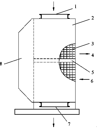
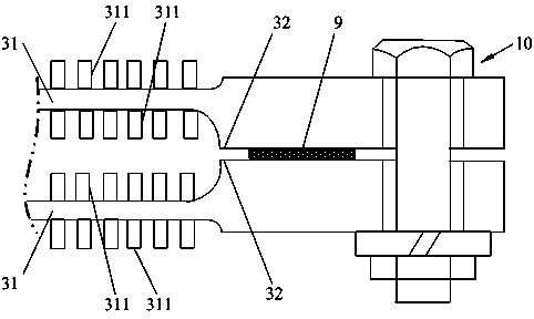
[0050] One of the specific implementations of a cast plate air preheater with baffle fins of the present invention, refer to figure 1 with figure 2 shown in figure 1 It includes a housing 2, a flue gas inlet 1, a flue gas outlet 7, an air inlet 6, an air outlet 4, and a heat exchange element 3 and a sealing structure 5 arranged in the housing 2. The heat exchange element 3 includes a plurality of Cast finned plate heat exchange unit, in figure 2 The cast finned plate heat exchange unit includes a base plate 31 and a fin group arranged on the base plate 31. The cast finned plate heat exchange unit is arranged in alignment with two base plates 31, and is sealed and connected through sealing bolts 10 respectively. The sealing surface 32 at its edge end. The heat exchange element 3 is made of casting or alloy. The two base plates 31 of the cast finned plate heat exchange unit are sealed and connected to the sealing surfaces 32 at both ends by sealing bolts 10 to form a cast f...

Embodiment 2

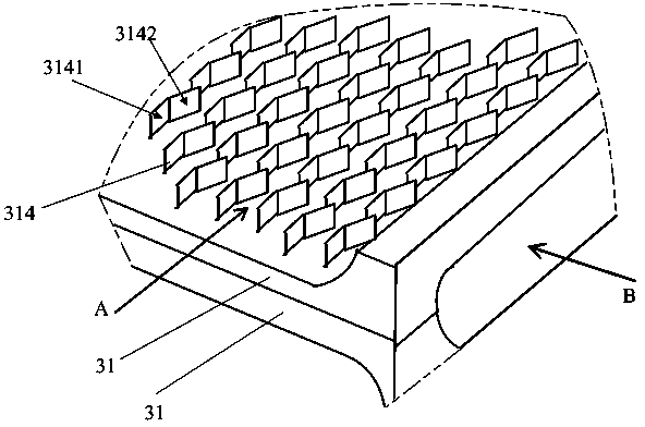
[0059] The second embodiment of a baffle-fin cast plate air preheater of the present invention, as image 3 with Figure 4 As shown, the main technical solutions of this embodiment are the same as those of Embodiment 1, and the features not explained in this embodiment are explained in Embodiment 1, and will not be repeated here. The difference between this embodiment and Embodiment 1 is that in the group of fins that include the baffle-shaped fins 314, the number of bends and the deflection angles of the base of the baffle-shaped fins 314 are set the same, and the baffle-shaped fins The base body of the sheet 314 is bent once to form a flow guide part 3141 and a flow guide part 3142 connected to each other, wherein the flow guide part 3141 is aligned with the direction of the longitudinal airflow channel ( Figure 4 The angle between the A direction) is the diversion angle φ 1. The angle between the diversion part 3142 and the diversion part 3141 is the deflection angle ...

Embodiment 3

[0061] The third specific embodiment of a baffle-fin cast plate air preheater of the present invention, as Figure 5 As shown, the main technical solutions of this embodiment are the same as those of Embodiment 1, and the features not explained in this embodiment are explained in Embodiment 1, and will not be repeated here. The difference between this embodiment and Embodiment 1 is that the fin groups arranged on one side or both sides of the substrate 31 are composed of single-fold manifold fins 315 and straight fins 312 bent once, and the single-fold manifold fins are bent once. The fins 315 and the straight fins 312 can be arranged in rows or mixed respectively.


PUM


Abstract

The invention relates to the technology of efficient heat-transfer energy-saving heat exchange equipment in mechanical equipment engineering, in particular to a wave-toothed fin casting plate-type air pre-heater. A baffling fin casting plate-type air pre-heater comprises a plurality of casting fin plate heat exchanging units. Each casting fin plate heat exchanging unit comprises a base board and a fin set arranged on the base board. Each fin set arranged on one base board comprises baffling fins. A base body of each baffling fin is perpendicularly and/or obliquely arranged on one base board. The base body of each baffling fin is at least continuously bent for once so that a flow guiding portion and at least one section of baffling portion which are sequentially connected can be formed. The bent directions of the adjacent baffling portions are reversed. Compared with the prior art, the baffling fins of the baffling fin casting plate-type air pre-heater change the direction of airflow along with the bent change of the baffling portions, when a large flow of air or smoke flows through the baffling fins at high speed, strong scratching motion is generated so that a turbulent flow can be generated, and therefore, stable laminar flows are prevented from being generated on the surfaces of the baffling fins, so that the heat transfer effect is good.

Description

technical field [0001] The invention relates to high-efficiency heat exchange and energy-saving heat exchange equipment technology in mechanical equipment engineering, in particular to a cast plate air preheater with baffle fins. Background technique [0002] Due to its resistance to flue gas dew point corrosion, cast plate air preheaters are often used to replace tubular air preheaters in the transformation of petrochemical, metallurgical, and energy power engineering machinery equipment. [0003] In the prior art, common cast plate air preheaters such as figure 1 and figure 2 As shown, its structure includes a casing 2 , a flue gas inlet 1 , a flue gas outlet 7 , an air inlet 6 , an air outlet 4 , and a heat exchange element 3 and a sealing structure 5 arranged in the casing 2 . Its working process is as follows: the flue gas enters from the flue gas inlet 1, and then discharges to the flue gas outlet 7 after passing through the heat exchange element 3 to exchange heat...

Claims


Application Information

Patent Timeline
Patent Type & Authority Applications(China)
IPC IPC(8): F23L15/02F28F1/12F28F13/02
CPCY02E20/34
Inventor 陈孙艺
Owner THE CHALLENGE PETROCHEM MACHINERY CORP
Why Eureka
Try Eureka