
Flight control system angle measuring device for airplane

An angle measurement device and technology of flight control system, applied in the direction of total factory control, total factory control, electrical program control, etc., can solve the problems of unable to measure parameters, low work efficiency, low measurement accuracy, etc., and achieve ultra-long working hours, highly repeatable effect

Inactive Publication Date: 2013-10-02
COMAC +1
View PDF2 Cites 9 Cited by
  • Summary
  • Abstract
  • Description
  • Claims
  • Application Information

AI Technical Summary

Problems solved by technology

This kind of measuring instrument has low measurement accuracy, and can only measure the rotation angle of the rotation axis parallel to the ground, and cannot measure parameters such as the rotation angle of the steering wheel, the rotation angle of the rudder surface, etc. The rotation axis has a certain angle with the ground
Moreover, when using this measuring instrument to measure, the work intensity of the test personnel is relatively high and the work efficiency is low. For example, in order to measure the angle of the rudder surface on the wing, the operator needs to stand on the wing for 2 to 3 hours, constantly Repeat the work of clearing and reading the measured value, and contact and report the data through the walkie-talkie
Therefore, the existing measuring instruments cannot meet the requirements of the flight control function test

Method used


Image

  • Flight control system angle measuring device for airplane
  • Flight control system angle measuring device for airplane

Examples


Embodiment Construction

[0017] As required, specific embodiments of the invention will be disclosed herein. However, it should be understood that the embodiments disclosed herein are merely typical examples of the invention, which can be embodied in various forms. Therefore, specific details disclosed herein are not to be considered limiting, but merely as a basis for the claims and as a representative basis for teaching one skilled in the art to variously employ the invention in any appropriate way in practice, This includes taking various features disclosed herein and combining features that may not be expressly disclosed herein.

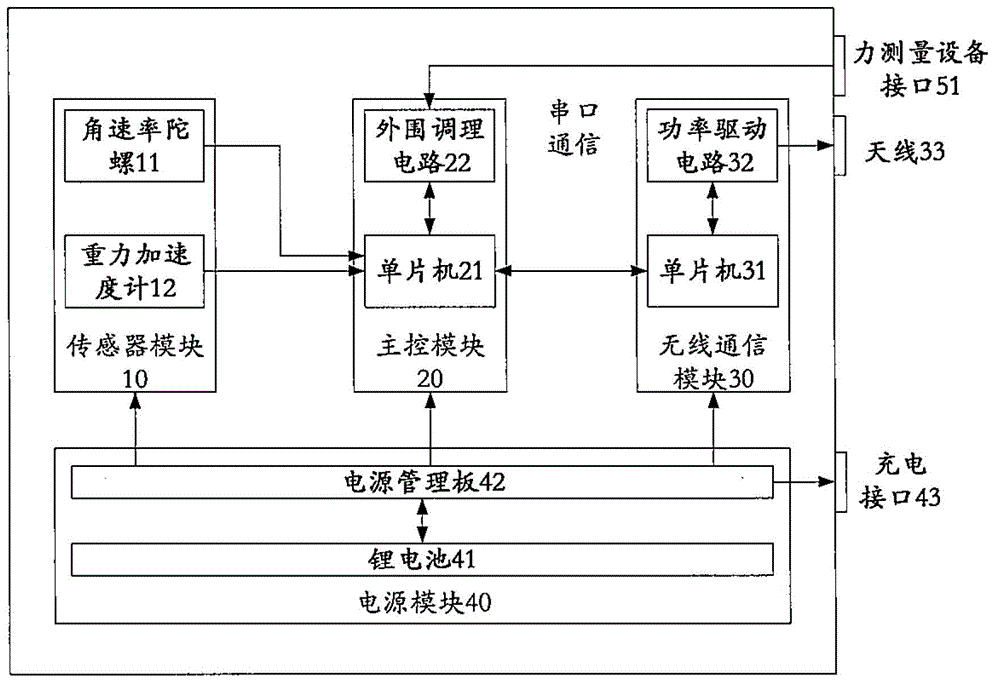
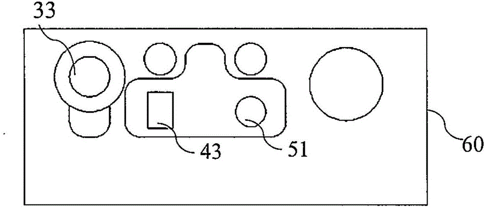
[0018] An aircraft flight control system angle measuring device according to a preferred embodiment of the present invention is implemented by an aircraft flight control system angle measuring instrument 100 . figure 1 A functional block diagram of the angle measuring instrument 100 is shown; figure 2 A side view of the goniometer 100 is schematically shown.

[0019]...


PUM


Abstract

The invention provides a flight control system angle measuring device for an airplane, which includes a sensor module, a master control module, a wireless communication module and a power source module, wherein the sensor module includes an angular velocity gyroscope and a gravity accelerometer; the master control module and the senor module are electrically connected to receive an angular velocity signal from the angular velocity gyroscope and a gravity acceleration signal from the gravity accelerometer and further convert the signals into deflection angle signals after calculation and processing; the wireless communication module and the master control module are electrically connected to receive a deflection angle signal from the master control module and further send the deflection angle signal to a remote control server; the power source module is electrically connected with all the modules respectively and used for providing electricity for the modules. The device can be used for measuring and calculating the angles simultaneously, and realizes the wireless transmission of measured data, remote measurement and control through being combined with the advantage of high dynamic response speed of the angular velocity gyroscope and the advantage of high multiplicity of the gravity accelerometer.

Description

technical field [0001] The invention relates to the angle measurement of an aircraft flight control system, in particular to a measuring instrument for measuring the rotation angles of a steering rod, a steering wheel, a rudder pedal and a rudder surface. Background technique [0002] When performing functional tests on the flight control system in the aircraft assembly workshop, it is necessary to measure the rotation angles of the steering column, steering wheel, rudder pedals and rudder surfaces. At present, the traditional two-axis gravity accelerometer inclination measuring instrument displayed by the traditional liquid crystal digital tube is usually used. This kind of measuring instrument has low measurement accuracy, and can only measure the rotation angle of the rotation axis parallel to the ground, and cannot measure parameters such as the rotation angle of the steering wheel, the rotation angle of the rudder surface, and other parameters that the rotation axis for...

Claims


Application Information

Patent Timeline
IPC IPC(8): G05B19/418
CPCY02P90/02
Inventor 孙鼎钫潘智昊张龙蔡云芳滕佳李青朱鉴萍吴熙杨龙周光友唐海龙
Owner COMAC
Learn More