Hollow floor air bag and construction method of cast-in-place hollow floors
A hollow floor and airbag technology, which is applied to the preparation of building components on site, the processing of floors, building materials, etc., can solve the problem of not conforming to the concept of eggshell bionic mechanics, limiting the mechanical performance and earthquake resistance of the floor, and the inability to guarantee Concrete pouring dense and other issues, to avoid floating and offset, enhance corrosion performance, easy to fix the effect
- Summary
- Abstract
- Description
- Claims
- Application Information
AI Technical Summary
Problems solved by technology
Method used
Image

Examples
Embodiment 1
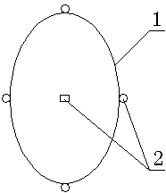
[0026] A hollow floor airbag, comprising an airbag body 1, the airbag body 1 is an eggshell-shaped ellipsoid structure, the airbag body 1 is provided with a fixing part 2, and the airbag body 1 is made of wear-resistant and corrosion-resistant canvas As a result, the fixing member 2 is a collar, and the collar is movably connected with the airbag body 1 .
[0027] Its construction method includes the following construction steps:
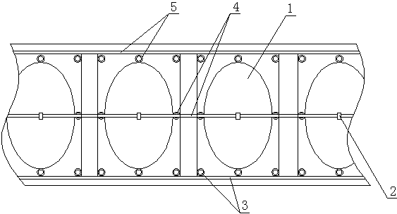
[0028] 1) According to the drawings and design requirements, mark the positioning, set up the formwork, lay the bottom steel bar 3, put the collar on the bottom steel bar and bind the bottom steel bar 3 so that the end of the binding wire faces downward;
[0029] 2) Reservation and pre-embedding of various pipelines according to design requirements;
[0030] 3) Bind the steel bars 4 of the densely ribbed beam so that the ends of the binding wires face down, install the airbag, fix the airbag body 1 with the collar, and fix the collar to the bottom ...
Embodiment 2
[0035] The difference between this embodiment and the first embodiment is that the fixing member 2 is a hoop.
[0036] Its construction method includes the following steps:
[0037] 1) According to the drawings and design requirements, mark the positioning, set up the formwork, lay the bottom steel bar 3 and bind it so that the end of the binding wire faces downward;
[0038] 2) Reservation and pre-embedding of various pipelines according to design requirements;
[0039] 3) Bind densely ribbed steel bars 4 so that the ends of the wires face down, install the airbag, and fix the airbag body 1 on the bottom steel bar 3 and the ribbed steel bar 4 through hoops;
[0040] 4) laying and binding the top layer of steel bars 5, and at the same time, the airbag body 1 is fixedly connected with the top layer of steel bars 5;
[0041] 5) Concrete is poured. Vibrate with a vibrator while pouring. Each airbag section is vibrated for 2-3 minutes to ensure that the concrete is dense and the...
Embodiment 3
[0044] The difference between this embodiment and Embodiment 1 is that the fixing part 2 is a U-shaped card. During construction, the airbag body 1 is fixed on the bottom steel bar 3, the rib beam steel bar 4 and the top layer steel bar 5 through the U-shaped card. .
[0045] Compared with the traditional hollow floor, the present invention has significantly improved engineering quality, cost, and construction period, and the compressive capacity is improved by more than 20% compared with the traditional hollow floor. The construction period can be effectively shortened by 30%, and the cost can be directly saved by more than 20%. It improves the quality of the project, shortens the construction period, and reduces the manpower, material and financial costs of project construction, bringing huge economic and social benefits.
PUM
 Abstract
Description
Claims
Application Information
 - Generate Ideas
- Intellectual Property
- Life Sciences
- Materials
- Tech Scout
- Unparalleled Data Quality
- Higher Quality Content
- 60% Fewer Hallucinations
Browse by: Latest US Patents, China's latest patents, Technical Efficacy Thesaurus, Application Domain, Technology Topic, Popular Technical Reports.
© 2025 PatSnap. All rights reserved.Legal|Privacy policy|Modern Slavery Act Transparency Statement|Sitemap|About US| Contact US: help@patsnap.com