Eureka AIR delivers breakthrough ideas for toughest innovation challenges, trusted by R&D personnel around the world.

4*4 nonblocking optical switching network based on five microring resonators

A micro-ring resonator, switching network technology, applied in the coupling of optical waveguides and other directions, can solve the problems of incompatibility with the requirements of multi-processor system interconnection network communication bandwidth, delay speed, power consumption, etc., to reduce cost and power. energy consumption, enhanced scalability, and the effect of streamlining the structure

Inactive Publication Date: 2015-04-29
ZHEJIANG UNIV
View PDF4 Cites 1 Cited by
  • Summary
  • Abstract
  • Description
  • Claims
  • Application Information

AI Technical Summary

Problems solved by technology

[0003] With the further improvement of multi-core processors' requirements for interconnection network performance, the limitations of electrical interconnection technology have become more and more obvious, and will gradually not meet the requirements of multi-processor system interconnection network communication bandwidth, delay speed, and power consumption.

Method used


Image

  • 4*4 nonblocking optical switching network based on five microring resonators
  • 4*4 nonblocking optical switching network based on five microring resonators
  • 4*4 nonblocking optical switching network based on five microring resonators

Examples


Embodiment Construction

[0020] In order to more clearly describe the purpose, technical solutions and advantages of the present invention, the present invention will be further described in detail below with reference to the accompanying drawings in conjunction with specific examples.

[0021] The invention utilizes the resonance characteristics of the active micro-ring resonator to design a novel switching network topology structure, and realizes a four-port low-loss non-blocking optical switching network.

[0022] Combine below Figure 1 to Figure 4 Details on how it works:

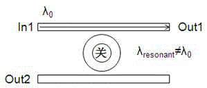
[0023] All the micro-rings in the switching network provided by the present invention have the same radius, but include two different structures, figure 1 and figure 2 Shown is a parallel waveguide microring switch, image 3 and Figure 4 Shown is a cross-waveguide microring switch. When the resonant wavelength of the micro-ring is consistent with the signal, the signal is coupled from one waveguide to another through th...


PUM


Abstract

The invention discloses a 4*4 nonblocking optical switching network based on five microring resonators. The 4*4 nonblocking optical switching network based on the five microring resonators comprises four crossing waveguide microring 1*2 photoswitches and one parallel waveguide microring 2*2 photoswitch, wherein the four crossing waveguide microring 1*2 photoswitches are respectively and directly connected with input and output ends; a first end input port 1 and a fourth end output port 4' are coupled by the microring resonator 1; not only the first end input port 1 and a third end output port 3', but also a fourth end input port 4 and a second end output port 2' are coupled by the microring resonator 2; a third end input port 3 and the second end output port 2' are coupled by the microring resonator 4; not only the third end input port 3 and a first end output port 1', but also a second end input port 2 and the fourth end output port 4' are coupled by the microring resonator 3; and the microring resonator 5 is used for connecting optical channels from the fourth end input port 4 to the first end output port 1' and from the second end input port 2 to the third end output port 3'. According to the 4*4 nonblocking optical switching network based on the five microring resonators, the nonblocking routing and switching of four bidirectional ports is completed through the five microring resonators; the microring resonators are decreased to five; in other words, the microring resonators are decreased by 37.5%; therefore, the insertion loss, the power consumption and the area are reduced; and crosses are reduced to six, so that the insertion loss and the crosstalk of the switching network are decreased, and the expandability of an optical interconnection network is enhanced.

Description

technical field [0001] The invention relates to an optical interconnection network architecture, in particular to a 4×4 non-blocking optical switching network based on 5 micro-ring resonators. Background technique [0002] With the development of semiconductor technology, the integration density of a single processor has increased significantly, and the processor has developed in the direction of multi-core and many-core, making the interconnection between cores one of the key factors restricting the overall performance of the processor. How to meet the requirements of delay and speed in the future multi-core system with low power consumption has become a major challenge in the field of integrated optoelectronics. [0003] With the further improvement of multi-core processors' requirements for interconnection network performance, the limitations of electrical interconnection technology have become more and more obvious, and will gradually not meet the requirements of multi-p...

Claims


Application Information

Patent Timeline
Patent Type & Authority Patents(China)
IPC IPC(8): G02B6/35
Inventor 张滨杨建义
Owner ZHEJIANG UNIV
Why Eureka
Eureka Blog
Learn More