Eureka AIR delivers breakthrough ideas for toughest innovation challenges, trusted by R&D personnel around the world.

Cold-end flexible cold chain structure of coaxial pulse tube refrigerator and manufacturing method

A pulse tube refrigerator, coaxial technology, applied in refrigerators, gas circulation refrigerators, refrigeration and liquefaction, etc., can solve the problems of adverse effects on the detection accuracy of cooled devices, reduced refrigerator efficiency, and damage to cooled devices. To achieve the effect of promoting conduction performance, reducing conduction distance and increasing efficiency

Inactive Publication Date: 2013-08-14
SHANGHAI INST OF TECHNICAL PHYSICS - CHINESE ACAD OF SCI
View PDF5 Cites 9 Cited by
  • Summary
  • Abstract
  • Description
  • Claims
  • Application Information

AI Technical Summary

Problems solved by technology

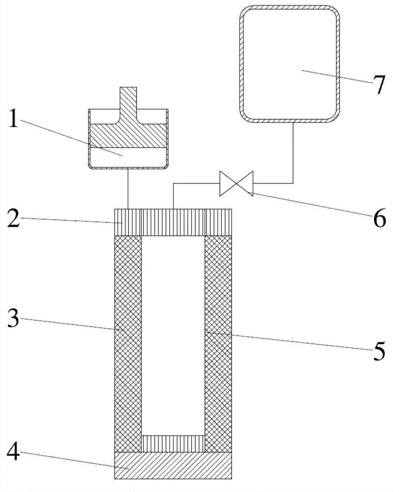
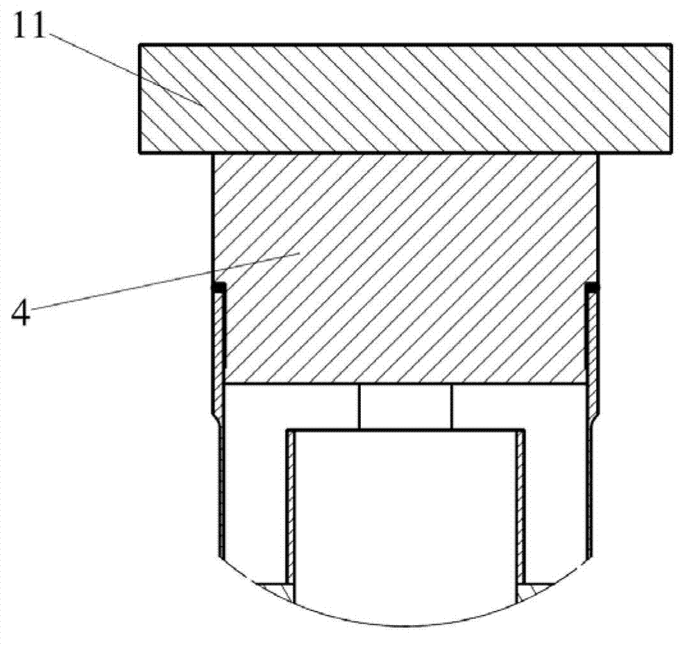
[0012] The first form, such as figure 2 As shown, when the refrigerator is in the working state, the vibration generated by the compressor will be transmitted to the refrigerator through the air guide tube, so that the cold head of the coaxial pulse tube refrigerator will also vibrate. Direct hard contact coupling, the vibration of the refrigerator will be directly transmitted to the cooled device, which will have a negative impact on the detection accuracy of the cooled device, and even destroy the cooled device in severe cases
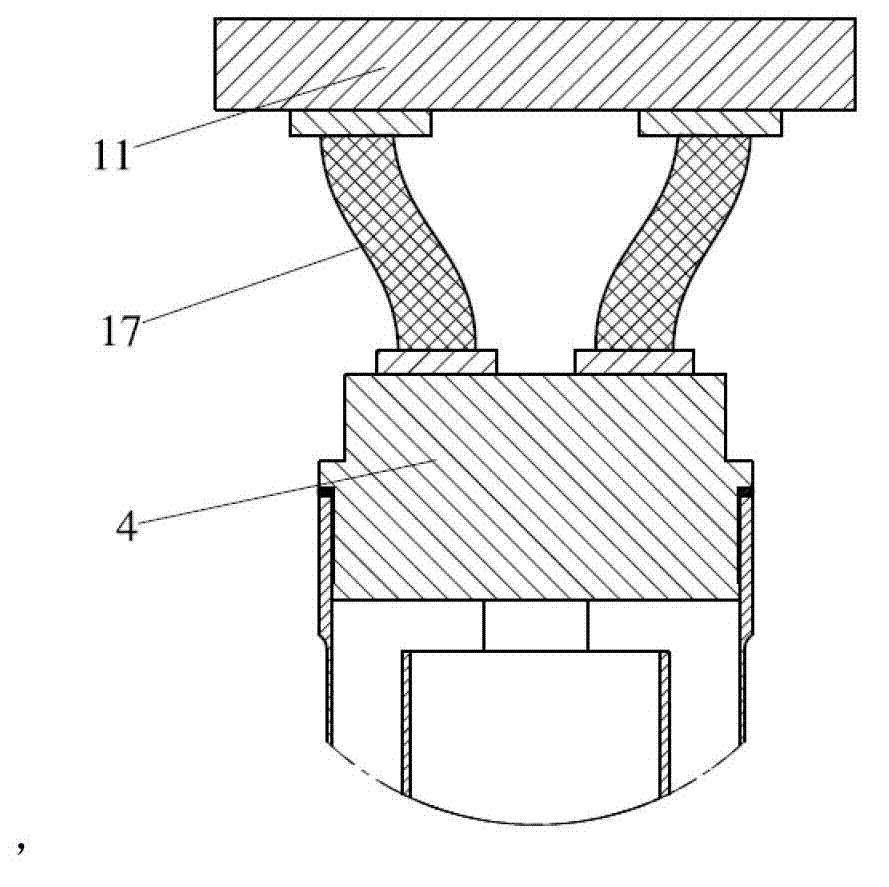
[0013] The second form, such as image 3 As shown, the cold head 4 is not bonded to the cooled device 11, but is connected with a soft copper strip 17. Although the flexible copper strip can eliminate the impact of the cold head vibration on the cooled device, a certain length of copper strip will It produces extremely considerable thermal resistance loss, which seriously reduces the efficiency of the refrigerator

Method used


Image

  • Cold-end flexible cold chain structure of coaxial pulse tube refrigerator and manufacturing method
  • Cold-end flexible cold chain structure of coaxial pulse tube refrigerator and manufacturing method
  • Cold-end flexible cold chain structure of coaxial pulse tube refrigerator and manufacturing method

Examples


Embodiment Construction

[0034] Below in conjunction with accompanying drawing and example the specific embodiment of the present invention is described in further detail:

[0035] Figure 4 It is a schematic structural diagram of the invented flexible cold chain at the cold end of a coaxial pulse tube refrigerator, including a cooled device 11 , a cold head cap 8 , a spring 9 , and a cold head 4 .

[0036] Figure 6 A cross-sectional schematic diagram of the cold head of a coaxial pulse tube refrigerator.

[0037] The invented flexible cold chain structure of the cold end of the coaxial pulse tube refrigerator is composed of four parts: the cold head 4, the cold head cap 8, the spring 9, and the cooled device 11. It is characterized in that the cold chain of the coaxial pulse tube refrigerator The cold head cap 8 is used as a link between the head 4 and the cooled device 11. A spring 9 is installed in the counterbore 16 at the upper end of the cold head 4. Under the extrusion of the spring 9, the u...


PUM


Abstract

The invention provides a cold-end flexible cold chain structure of a coaxial pulse tube refrigerator and a manufacturing method. The structure comprises a cold head, a cold head cap, a spring and a cooled device. An upper-end plane of the cold head cap is jointed with the cooled device, the cold head cap is mounted at the top of the cold head, the spring is mounted between the cold head and the cold head cap to enable the two to contact and to be capable of moving vertically, and a buffering space is formed between the cold head and the cold head cap. A small hole connected with the outside is arranged at the bottom of a countersink of the upper end of the cold head so as to extract remaining air in a closed region between the cold head and the cold head cap. Since the cold head cap supported by the spring is mounted between the cold head and the cooled device, the cold head is jointed with the cooled device closely, and influences of slight vibration on the cooled device when the refrigerator works are weakened. The small hole leading to the outside is added inside the cold head, so that condensate ice crystals are avoided, loss in a cold transfer process is reduced, and quite positive effects on application and popularization of coaxial pulse tube refrigerators are achieved.

Description

technical field [0001] The invention relates to a pulse tube refrigerator, in particular to a flexible cold chain structure and a manufacturing method at the cold end of a coaxial pulse tube refrigerator. Background technique [0002] Because there are no moving parts at low temperature, the pulse tube refrigerator has the advantages of small mechanical vibration, small electromagnetic interference, and long life. Furthermore, the structure is simple, the reliability is high, the impact resistance of the cold head is strong, and the control circuit is simple, so it has wide application value in aerospace, mobile communication base station, medical treatment and other fields. [0003] According to the different arrangements of the pulse tube and the regenerator of the pulse tube refrigerator, it is generally divided into three types of arrangements, namely linear, U-shaped, and coaxial. The U-type is to arrange the pulse tube and the regenerator side by side and connect them...

Claims


Application Information

Patent Timeline
Patent Type & Authority Applications(China)
IPC IPC(8): F25B9/14
CPCF25B9/145F25B2309/1406
Inventor 党海政周炳露
Owner SHANGHAI INST OF TECHNICAL PHYSICS - CHINESE ACAD OF SCI
Why Eureka
Eureka Blog
Learn More