
Bolt type aluminium electrolytic capacitor with high reliability and high temperature resistance

An aluminum electrolytic capacitor, reliability technology, applied in the direction of capacitor electrodes, capacitor parts, etc., can solve problems such as not being able to meet the requirements, and achieve the effects of improving product reliability, improving heat dissipation performance, and reducing the conduction distance

Active Publication Date: 2014-03-19
SHANGHAI YONGMING ELECTRONICS
View PDF5 Cites 1 Cited by
  • Summary
  • Abstract
  • Description
  • Claims
  • Application Information

AI Technical Summary

Problems solved by technology

Although these methods can play a certain heat dissipation effect, they are far from meeting the requirements.

Method used


Image

  • Bolt type aluminium electrolytic capacitor with high reliability and high temperature resistance
  • Bolt type aluminium electrolytic capacitor with high reliability and high temperature resistance
  • Bolt type aluminium electrolytic capacitor with high reliability and high temperature resistance

Examples


Embodiment 1

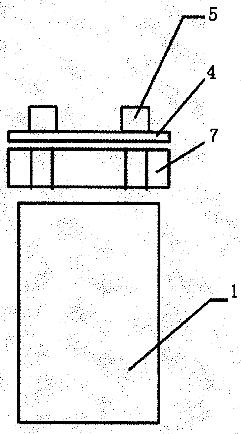
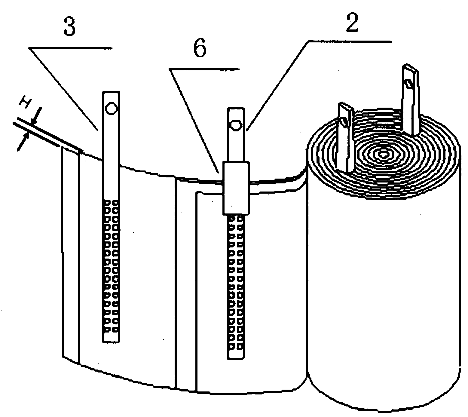
[0020] like figure 1 As shown, the present invention provides a bolt-type aluminum electrolytic capacitor, including a capacitor element 1, combined with figure 2 The capacitor element 1 is composed of the first electrolytic paper, the negative electrode foil with the negative conductive foil strip 3 riveted by cold pressure riveting or punching, the first electrolytic paper, the positive electrode foil with the positive conductive foil strip 2 riveted by cold pressure riveting or punching Layered and wound. The difference between the capacitor element 1 in the present invention and the existing capacitor elements is that the upper edge of the negative electrode foil extends upwards to expose the height of the upper edge of the first electrolytic paper to H, H≥0, so that the inside of the capacitor element 1 Heat can be conducted out through the negative electrode foil with the shortest distance. In order to conduct heat, a heat sink 7 is arranged above the capacitor elemen...

Embodiment 2

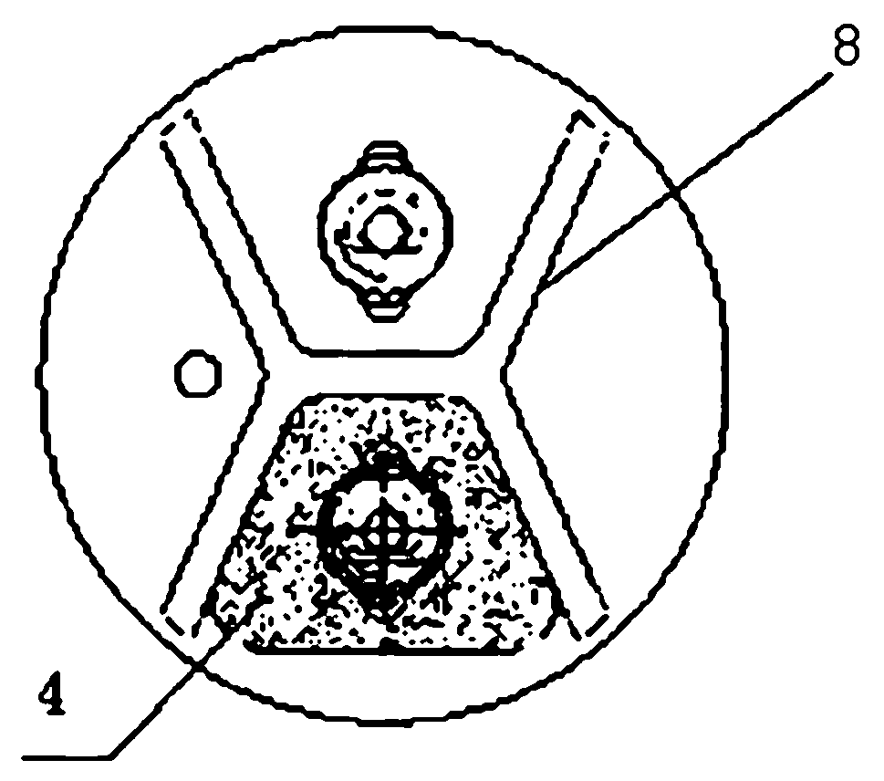
[0023] The difference between this embodiment and Embodiment 1 is that the cover plate 4 adopts a heat dissipation cover plate, and the heat dissipation cover plate can be made of aluminum. In order to ensure product performance, the purity of the aluminum material used in this example is 99.99%, and its structure is as follows: image 3 As shown, there is an H-shaped rib 8 at the bottom of the cover plate 4 . At this time, the structure of the heat sink 7 is as follows: Figure 4 As shown, a slot 9 is provided on it, and the reinforcing rib 8 is snapped into the slot 9, so that the heat sink 7 and the cover plate 4 can be assembled conveniently, which is convenient for production. There is a negative chaff hole 11 on the heat sink 7, so that all the negative chaff 3 can pass through the hole. There is also a positive foil grid 12 on the heat sink 7 for passing the positive foil 2 , and a hole in the positive foil grid 12 corresponds to one positive foil 2 . In order to incr...


PUM


Abstract

The invention relates to a bolt type aluminium electrolytic capacitor with high reliability and high temperature resistance. The capacitor comprises a capacitor element which is formed by folding and coiling a positive electrode foil on which a positive foil guide strip is fixed, a negative electrode foil on which a negative foil guide strip is fixed and first electrolytic paper. The capacitor is characterized in that the upper edge of the negative electrode foil extends upward to expose outside the upper surface of the capacitor element, an insulated structure is sleeved outside the positive foil guide strip, a heat radiation pin is arranged between the capacitor element and a cover plate, and both the negative foil guide strip and the positive foil guide strip pass through the heat radiation pin and then are connected with the corresponding cover plate terminals. The heat radiation performance of the bolt type aluminium electrolytic capacitor provided by the invention is greatly raised. In the actual use of the whole assembled machine, the surface temperature rise is less than 2 DEG C, a product with a service life of 3000 hours at 85 DEG C is raised to a service life of 6000 hours at 85 DEG C, a product with a service life of 3000 hours at 105 DEG C is raised to a service life of 6000 hours at 105 DEG C, and the product reliability is greatly improved.

Description

technical field [0001] The invention relates to a bolt type aluminum electrolytic capacitor, which belongs to the technical field of aluminum electrolytic capacitors. Background technique [0002] With the national call for energy saving and emission reduction, the application of power supplies and frequency converters is becoming more and more extensive. Reliability puts forward higher and higher demands. Aluminum electrolytic capacitors are one of the most important components in power supplies and frequency converters. Traditional aluminum electrolytic capacitors include an external aluminum shell with a prime inside the aluminum shell. The top of the aluminum shell is a cover plate made of phenolic resin. The cover plate terminal, the positive chaff strip and the negative chaff strip of the element are respectively connected to the respective cover plate terminals. The production process of the element is generally as follows: put the positive conductor foil and the ne...

Claims


Application Information

Patent Timeline
Patent Type & Authority Applications(China)
IPC IPC(8): H01G9/004H01G9/04
Inventor 王永明王小东
Owner SHANGHAI YONGMING ELECTRONICS
Learn More