Injection mould with rapidly-replaced mould cores

An injection mold and mold core technology, applied in the field of molds, can solve problems such as the influence of replacement efficiency, low tensile strength, and high labor intensity of operators, so as to reduce the requirements of operating proficiency, reduce physical requirements, and improve mold replacement efficiency. Effect

Active Publication Date: 2015-07-15
GUANGZHOU MODERN PLASTIC CO LTD
View PDF5 Cites 1 Cited by
  • Summary
  • Abstract
  • Description
  • Claims
  • Application Information

AI Technical Summary

Problems solved by technology

[0005] ⑴. The injection molding process of various splines is different, and the existing molds gather all kinds of splines in the same mold, which cannot meet the injection molding process requirements of various splines at the same time, and it is easy to distort the quality of the test splines. Can not objectively and truly reflect the performance of the material
For example, stretching splines have certain requirements on the tendency of molecules, while relatively thick splines require a relatively long holding time to minimize the shrinkage of the splines, and injection molding requires fast The injection speed can fill the mold cavity. Obviously, no matter what injection molding process is used, it is impossible to meet the injection molding process requirements of all splines at the same time.
[0006] ⑵. Various splines of the same material need to test many performance indicators, and different materials have different test items in different periods, so it is impossible to produce standard splines that require all test indicators with the same mold.
[0008] ⑴. The mold is bulky and heavy, the assembly with the injection molding machine is complicated, and the labor intensity of the operator is very high, so that the whole process of changing the mold often takes about 45 minutes to an hour. Moreover, the specific conditions of the injection molding machine and the mold, the operator The physical fitness and operating proficiency of the operator will have an impact on the replacement efficiency, and directly affect the production efficiency of the spline
[0009] ⑵. Existing molds have relatively limited applicability to materials, and are only suitable for materials with moderate hardness. When the mold is opened to take out the spline, the ejection method is usually used, that is, several parts of the spline are selected as the ejection method. If the hardness of the spline material is high, it will be difficult to remove the mold due to the adhesion between the spline and the cavity wall of the mold. At this time, if the mold is forcibly removed, the performance of the spline will be affected. During the test, the spline is easy to break in the transition section between the clamping section and the working section; if the hardness of the spline material is low, the spline will be deformed after demolding, which is not conducive to the test of the performance index of the spline
The spline deformation mentioned above means that the spline produces a demoulding slope, that is, the cross-sectional shape of the spline is an inverted trapezoid with a large top and a small bottom. When calculating the tensile strength (MPa), it is necessary to calculate the area of ​​the cross-section For measurement, vernier calipers are generally used for measurement. However, vernier calipers can only measure the value of the top side (longer side), so the obtained cross-sectional area will be larger than the actual value, and the final tensile strength will be smaller than the actual data. The test data is inaccurate, and it is easy to cause the splines that are originally up to the standard to be measured as substandard splines. In this case, it is quite unfavorable to the manufacturer that provides the splines

Method used


Image

  • Injection mould with rapidly-replaced mould cores
  • Injection mould with rapidly-replaced mould cores
  • Injection mould with rapidly-replaced mould cores

Examples


Embodiment 1

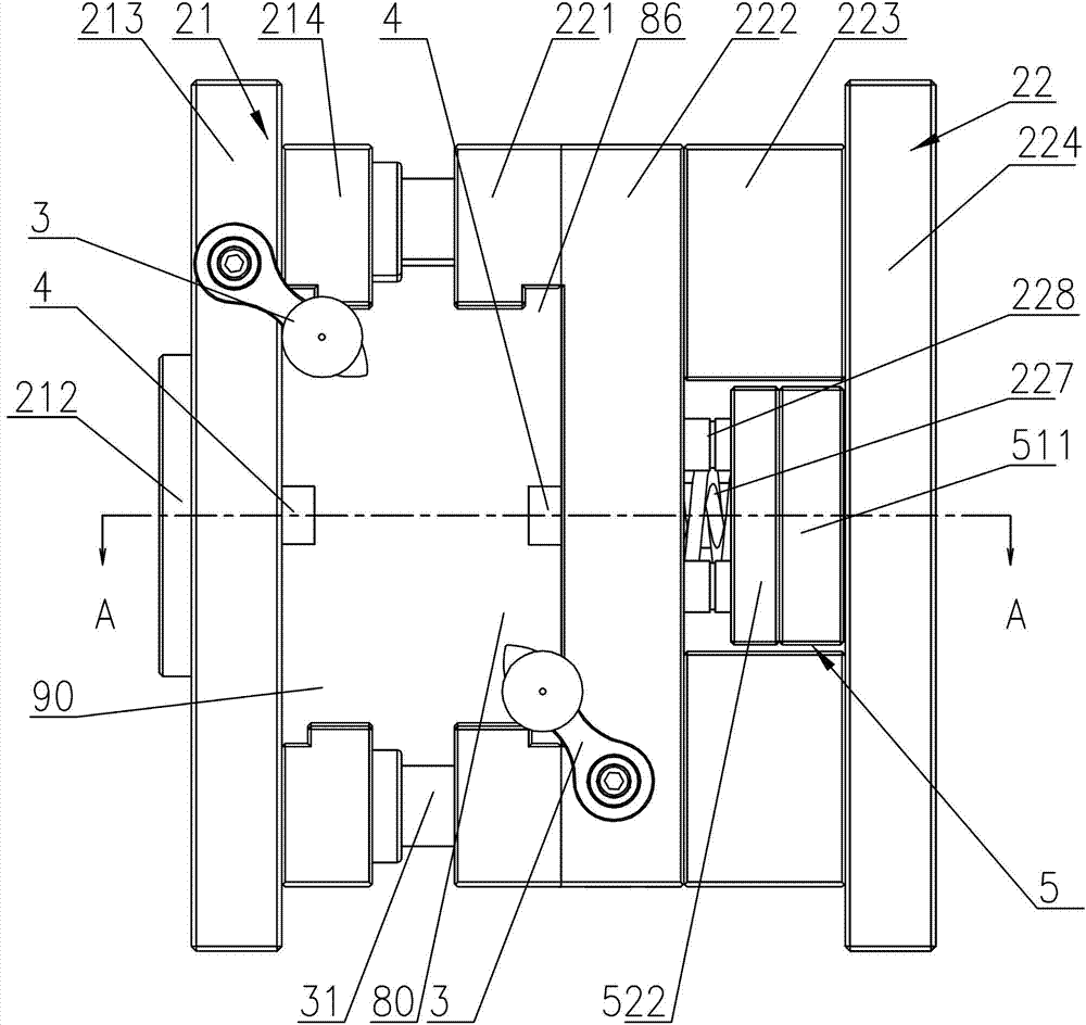
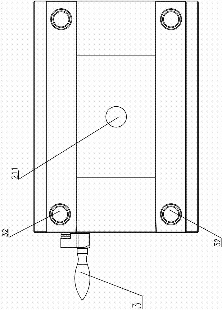
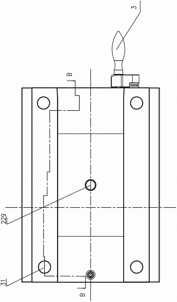
[0055] Such as Figure 1-12 , Shown in 19, is a kind of injection mold that can replace mold core quickly of the present invention, in the present embodiment, is to make test standard spline, seeFigure 9 , the injection mold is composed of a movable mold and a fixed mold, wherein the movable mold and the fixed mold include molding parts, a push-out mechanism, a mold guide part and a pouring system, and the main body of the movable mold is mounted on the movable mold holder 22 by a movable mold holder 22 The movable mold core 12 is composed of the fixed mold body, and the fixed mold body is composed of the fixed mold frame 21 and the fixed mold core 11 movably installed on the fixed mold frame 21. The movable mold frame 22 and the fixed mold frame 21 are collectively referred to as the mold frame, and the movable mold core 12 The mold core and the fixed mold core 11 are collectively referred to as the mold core. The mold core is a movable molding part separated from the mold fra...

Embodiment 2

[0076] Such as Figures 13 to 18 As shown, the difference between this embodiment and embodiment 1 is: the injection mold cavity on the mold core is different, see Figure 15 , the injection molded part suitable for the mold core of this embodiment is a cantilever beam 91, a bending standard test sample 92, and an impact standard test sample 93, and two movable inserts 70, 71 are arranged on the clamping surface of the fixed mold core 11, The movable inserts are centered on the pouring hole (that is, the inner channel 54 of the sprue bushing) and are distributed front and rear. There are two mold cavities 73 on the mold clamping surface of the movable mold core 12. The two mold cavities on the movable mold core are connected with the The movable inserts 70 and 71 correspond to each other. When the mold is closed, the movable inserts are located in the mold cavity of the movable mold core to form 4 injection molding chambers for injection molding a single injection molded part,...


PUM


Abstract

The invention discloses an injection mould with rapidly-replaced mould cores. The injection mould is composed of a movable mould and a stationary mould, wherein a main body of the movable mould is composed of a movable mould base and a movable mould core movably arranged on the movable mould base; a main body of the stationary mould is composed of a stationary mould base and a stationary mould core movably arranged on the stationary mould base; the butt joint faces of the movable mould base and the stationary mould base are respectively provided with a mould core mounting sliding chute which horizontally extends from front to back; at least the front ends of the mould core mounting sliding chutes are provided with plug-in mounting holes for mounting or dismounting the mould cores; the mould cores are provided with tracks matched with the mould core mounting sliding chutes so as to move along the mould core mounting sliding chutes; and the mould cores are inserted to or dismounted from the mould core mounting sliding chutes on the mould bases through the plug-in mounting holes, thus the mould cores are replaced. According to the invention, only one set of mould base needs to be manufactured to be matched with the mould cores of different cavities which are manufactured according to spline standards tested based on different performance indexes; the mould replacing operation is easier and more convenient than that of the prior art, so that the mould replacing time is greatly shortened; and the manufacturing cost of various test spline moulds can also be greatly reduced.

Description

technical field [0001] The invention relates to a mould, in particular to an injection mould, which can quickly replace the mold core, and is suitable for making plastic standard test specimens, plastic products, rubber products and the like by injection molding. Background technique [0002] Synthetic materials (including modified materials such as plastics and rubber) are one of the important materials used in people's daily life. In recent years, with the continuous improvement of the technical level in various fields, the requirements for synthetic materials have also increased accordingly. For example, in the automotive field, some auto parts must have the performance of high temperature resistance and high strength, while some parts used as interior decoration It is required to have good surface finish, small specific gravity and considerable toughness; in the field of household appliances, the plastic casing of electrical products is required to have a certain appeara...

Claims


Application Information

Patent Timeline
Patent Type & Authority Patents(China)
IPC IPC(8): B29C45/26B29C33/30
Inventor 陈琪
Owner GUANGZHOU MODERN PLASTIC CO LTD
Why Eureka
Try Eureka