
A lead-acid storage battery grid whose surface layer is doped with rare earth elements and its preparation method

A technology of lead-acid batteries and rare earth elements, which is applied in the direction of electrode carriers/collectors, etc., can solve the problems of high gas evolution rate, large grid corrosion rate, and increased battery water loss rate, and achieve high hydrogen evolution and oxygen evolution overpotential, The effect of high corrosion resistance and high specific gravity capacity

Active Publication Date: 2015-08-05
JIANGSU OLITER ENERGY TECH
View PDF11 Cites 0 Cited by
  • Summary
  • Abstract
  • Description
  • Claims
  • Application Information

AI Technical Summary

Problems solved by technology

But their disadvantages are large resistance, high gas evolution rate, increased battery water loss rate, and accelerated grid corrosion
Especially in the deep cycle, the corrosion rate of the grid is greater, and the battery capacity will decrease significantly with the later stages of the battery cycle

Method used


Image

  • A lead-acid storage battery grid whose surface layer is doped with rare earth elements and its preparation method

Examples


Embodiment 1

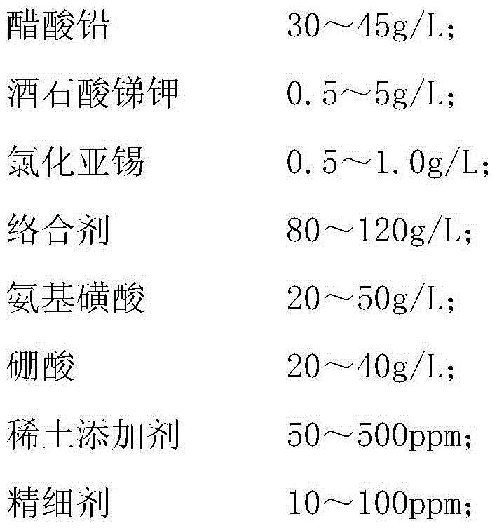
[0029] A method for preparing a lead-acid battery grid whose surface layer is doped with rare earth elements. In this embodiment, metal titanium is used as the base material, and the alloy surface layer of Pb-Sb-Sn doped with composite rare earth elements is obtained by plating in an electroplating solution. , the specific electroplating solution and working parameters are as follows: 40g / L of lead acetate, 2.2g / L of antimony potassium tartrate, 0.7g / L of stannous chloride, 120g / L of citric acid, and 35g / L of boric acid are mixed and dissolved completely. Adjust the pH to about 5, add 100ppm of cerium oxide, 100ppm of yttrium oxide and 100ppm of neodymium oxide, and add 20ppm of butynol propoxy compound BMP under the condition of sufficient stirring, and the plating solution configuration is completed. The lead plate is used as the anode, the titanium metal substrate is used as the cathode, and the electroplating is carried out in the charged tank (connected to the negative pol...

Embodiment 2

[0031] The present embodiment takes metal copper as the base material, and is electroplated in the following plating solution: lead acetate of 32g / L, potassium antimony tartrate of 4.5g / L, stannous chloride of 0.5g / L, citric acid 120g / L, 35g After the / L boric acid is mixed and dissolved completely, adjust the pH to about 5, add 200ppm of cerium oxide, 100ppm of yttrium oxide and 50ppm of neodymium oxide, and add 10ppm of N,N-diethylpropyne under the condition of full stirring After amine DEP, the plating solution configuration is complete. The lead plate is used as the anode, the copper metal substrate is used as the cathode, and the electroplating is carried out in the charged tank (connected to the negative pole of the DC power supply). The current density is controlled within the range of 2-3A / dm2, and the electrodeposition is 5-10 minutes, and 3-10 microns can be obtained. The main component of the coating is lead, and it contains about 3.5% of the metal antimony, 0.5...


PUM

PropertyMeasurementUnit
thicknessaaaaaaaaaa
current densityaaaaaaaaaa

Abstract

The invention discloses a lead-acid battery grid doped with rare earth elements on the surface layer and a preparation method thereof. A positive grid comprises a matrix and a surface layer, wherein the surface layer is formed by plating and mainly comprises the following components by mass percent: 95-98 percent of Pb (plumbum), 2-5 percent of Sb (stibium), 0.03-0.1 percent of Sn (stannum), 0.01-0.05 percent of composite rare earth and the balance of unavoidable impurities, wherein the composite rare earth comprises the following components by mass percent: 52-67 percent of Ce (cerium), 12-22 percent of Y (yttrium) and 10-20 percent of Nd (neodymium). The lead-acid battery grid disclosed by the invention not only has higher corrosion resistance, but also has higher overpotential of hydrogen and oxygen evolution, so that a battery electrolyte is stable and free of maintenance; and meanwhile, batteries prepared by using the grid disclosed by the invention have higher specific weight capacity.

Description

technical field [0001] The invention belongs to the technical field of lead accumulators, in particular to a long-life and maintenance-free electrode grid. Background technique [0002] At present, the traditional lead-acid battery grid whose surface layer is doped with rare earth elements is made of lead-tin alloy or lead-antimony alloy and cast. But their disadvantages are large resistance, high gas evolution rate, increased battery water loss rate, and accelerated grid corrosion. Especially in the deep cycle, the corrosion rate of the grid is greater, and the battery capacity will decrease significantly with the later stage of the battery cycle. Contents of the invention [0003] Purpose of the invention: In view of the above-mentioned existing problems and deficiencies, the purpose of the present invention is to provide a lead-acid battery grid whose surface layer is doped with rare earth elements and its preparation method. The grid prepared by this method has excell...

Claims


Application Information

Patent Timeline
Patent Type & Authority Patents(China)
IPC IPC(8): H01M4/68
CPCY02E60/10
Inventor 袁平谭明铭张静严学庆
Owner JIANGSU OLITER ENERGY TECH
Learn More