
Condensation enhancement and heating type seawater desalter

A heating type, water receiving tank technology, applied in the direction of heating water/sewage treatment, seawater treatment, general water supply saving, etc., can solve the problems of small contact area, large heat loss, slow heat dissipation, etc., to improve the contact area, Improved heating capacity and simple structure

Inactive Publication Date: 2014-03-19
LOGISTICAL ENGINEERING UNIVERSITY OF PLA
View PDF4 Cites 0 Cited by
  • Summary
  • Abstract
  • Description
  • Claims
  • Application Information

AI Technical Summary

Problems solved by technology

But at the same time, it also has certain defects. In the general tubular seawater desalination device, when the seawater is evaporating and condensing, the evaporated water vapor rises to the top of the external condensing pipe to condense. The top of the ordinary condensing pipe is a dome, which is different from The contact area of ​​the outside air is small, and the heat energy is dissipated slowly, which makes the seawater condense more slowly
And the heating tube used by the common tubular seawater desalination device is a common "U"-shaped tube, with one end of the oil inlet and one end of the oil outlet, through which the hot oil or water flows to heat the water in the water tank, but Ordinary "U"-shaped tubes have a small contact area with the seawater in the water tank, resulting in slow heating of the seawater. At the same time, the heated seawater exchanges heat with the outside through the tube wall, resulting in a large heat loss. These defects are to a certain extent Reduced desalination speed

Method used


Image

  • Condensation enhancement and heating type seawater desalter
  • Condensation enhancement and heating type seawater desalter
  • Condensation enhancement and heating type seawater desalter

Examples


Embodiment Construction

[0014] The present invention will be further described below in conjunction with drawings and embodiments.

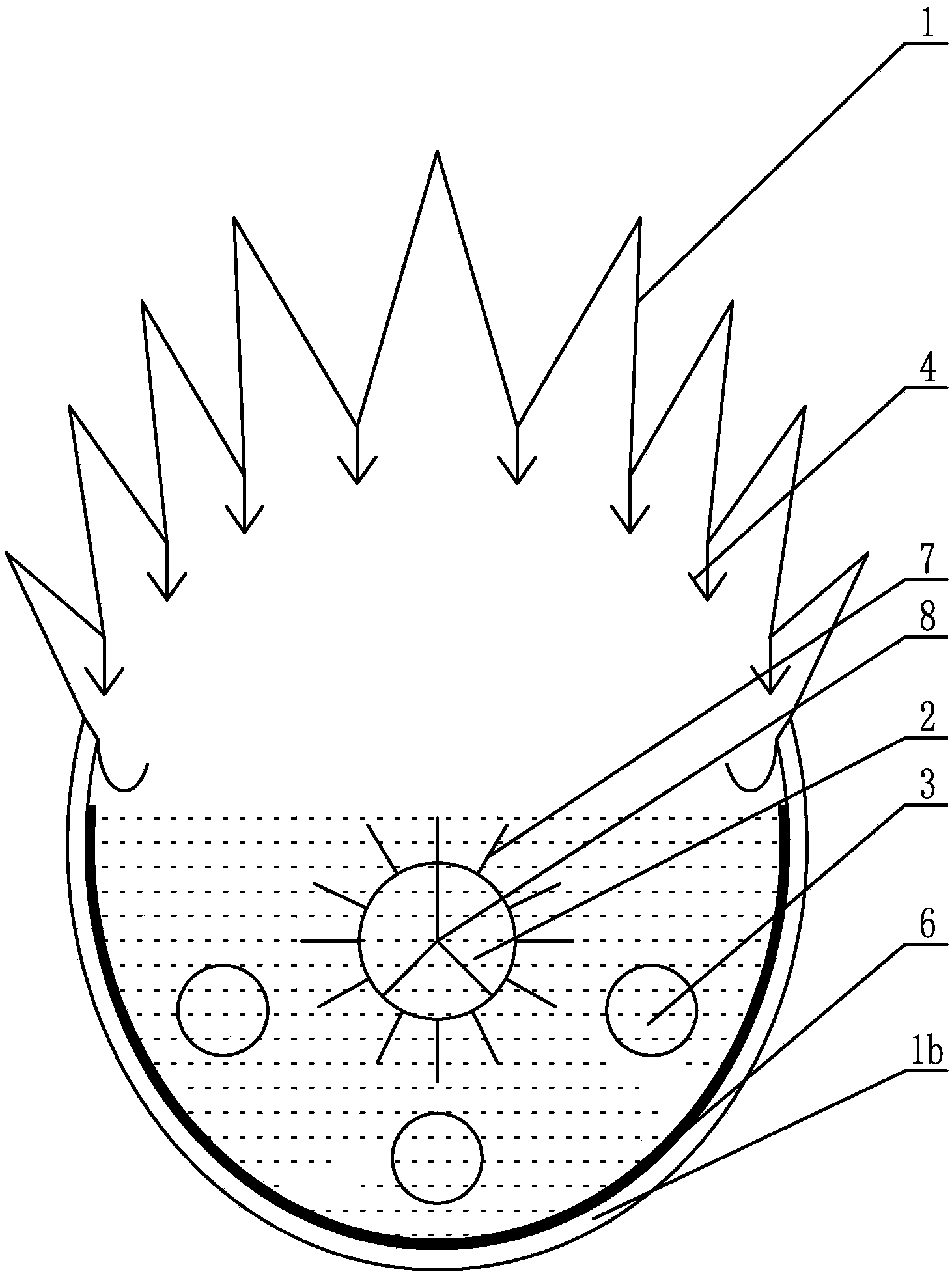
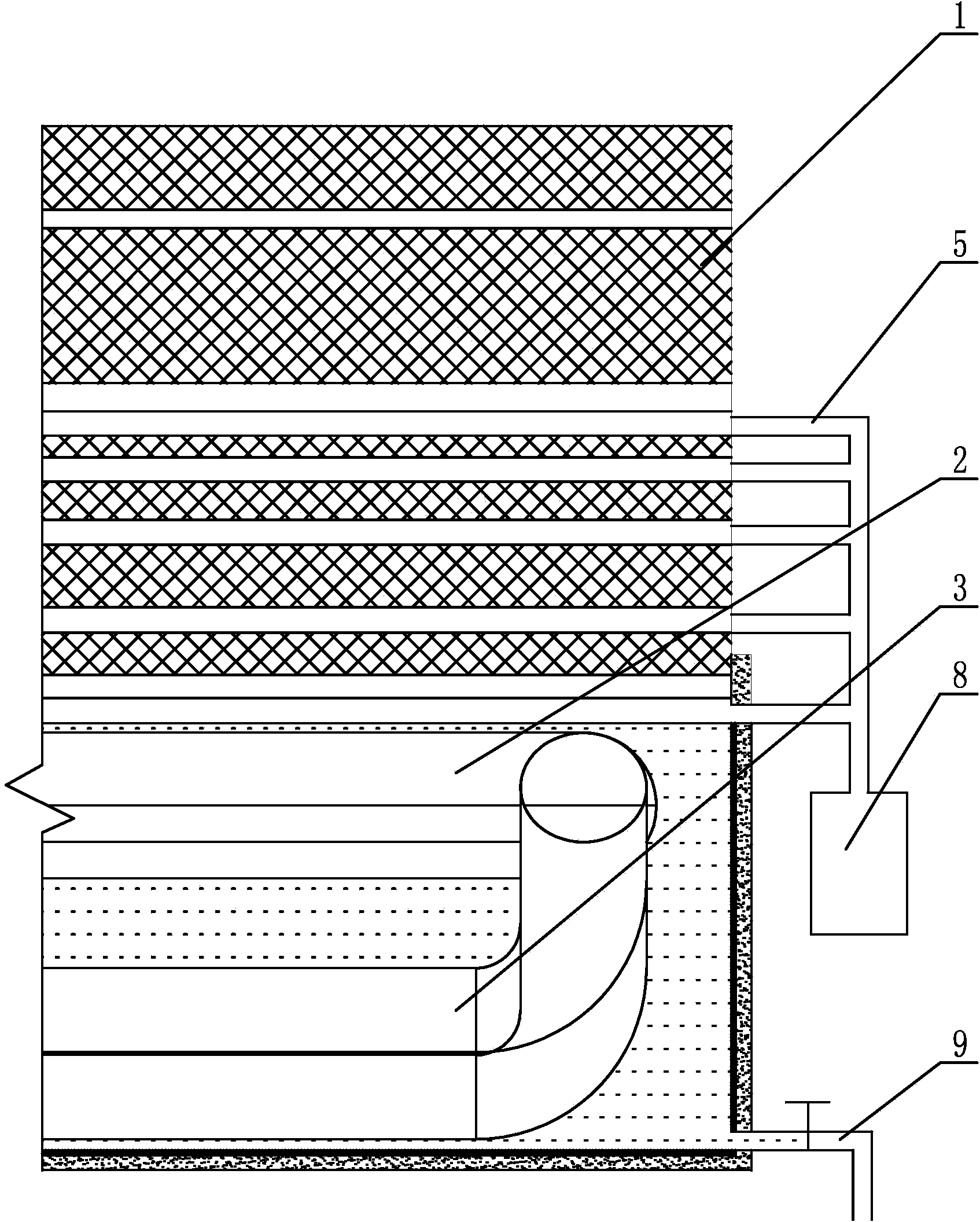
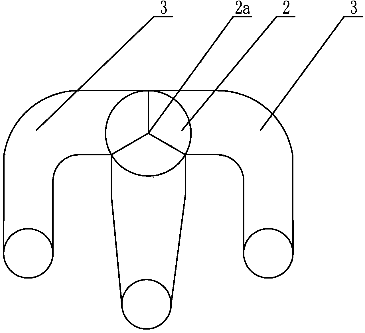
[0015] Such as figure 1 , figure 2 with image 3 As shown, the present invention is composed of shell 1, oil inlet pipe 2, oil outlet pipe 3, water receiving tank 4, fresh water output pipe 5, thermal insulation layer 6 and cooling ribs, and the upper half of the shell 1 is arc-shaped and sawtooth A water receiving tank 4 is arranged below each groove of the sawtooth, and the water receiving tank 4 is fixedly connected in the housing 1 along the axial direction, and one end of each of the water receiving tanks 4 is connected with the fresh water output pipe 5 . The bottom of the shell 1 is a vacuum chamber 1b, and an insulation layer 6 is installed on the inner wall of the bottom of the shell 1, and the bottom of the shell 1 is provided with a concentrated brine output pipe 9, and the concentrated brine output pipe 9 communicates the shell 1 with the outside world. ...


PUM


Abstract

The invention discloses a condensation enhancement and heating type seawater desalter comprising a casing and a heating pipe, wherein the lower half part of the casing is a vacuum cavity, the inner wall of the casing is additionally provided with a heat insulation layer, and the lower part of the casing is provided with an oil inlet pipe and an oil outlet pipe; an oil outlet of the oil inlet pipe is communicated with an oil inlet of the oil outlet pipe, and the oil inlet pipe and the oil outlet pipe are arranged in the casing along the axial direction; and the upper half part of the casing is of an arc saw tooth shape, a water receiving tank is arranged below each groove of saw teeth and fixedly connected to the inside of the casing along the axial direction, and the end head of one end of each water receiving tank is connected with a freshwater outlet pipe. Based on the desalter, the contact area between the top of the casing and the outside air is increased, the speed that steam condenses into water is improved, the heat insulation layer and the vacuum cavity reduce heat radiation of seawater, the capacity of heating seawater by the oil inlet pipe is improved through heat radiation ribs, the energy efficiency is improved; and meanwhile, the desalter has the characteristics of energy saving, environment protection, simple structure and the like.

Description

technical field [0001] The invention relates to the technical field of seawater desalination and water treatment, in particular to a seawater desalinator with enhanced condensation effect and heating effect. Background technique [0002] The shortage of fresh water resources in the world has become a problem that people are increasingly concerned about. Seawater desalination, as an open source and incremental technology of water resources, has become an important way to solve the global water resource crisis. Seawater desalination is to use seawater desalination to produce fresh water. At present, the most used seawater desalination technologies in my country mainly include reverse osmosis and distillation. Among them, reverse osmosis is also called ultrafiltration. The semipermeable membrane through which the solute passes separates seawater from freshwater, but the cost of reverse osmosis is relatively high, and it has the disadvantages of large one-time investment and larg...

Claims


Application Information

Patent Timeline
Patent Type & Authority Patents(China)
IPC IPC(8): C02F1/04C02F103/08
CPCY02A20/124
Inventor 陈志莉姚洋杨毅杨嘉熊开生肖晓任振杰
Owner LOGISTICAL ENGINEERING UNIVERSITY OF PLA
Learn More