
Constant humidity type classification heat exchange dewatering and water-wind sensible heat multistage utilization relaxation heat setting machine

A technology of graded heat exchange and heat setting machine, which is applied in dryers, lighting and heating equipment, textiles and papermaking, etc., can solve the problems of inability to maintain pressure difference, deteriorate heat exchange efficiency, and insufficient displacement, and reduce heat Losses, heat pollution reduction, steam consumption reduction effect

Inactive Publication Date: 2013-05-08
YIHENG ENERGY SAVING TECH JIANGSU
View PDF11 Cites 1 Cited by
  • Summary
  • Abstract
  • Description
  • Claims
  • Application Information

AI Technical Summary

Problems solved by technology

[0003] The shortcomings of this relaxation heat setting machine are: (1) According to different products, there are three levels of steam pressure, but only one steam trap is installed, and the steam trap can only work normally under a certain pressure. , cannot maintain the pressure difference required for normal work, either the displacement is not enough, or the steam leakage is serious
(2) The waste heat of the condensed water discharged by the steam trap needs to be utilized by external users. When there is no suitable user, it will inevitably be emptied and wasted
(3) Pollutants carried by the return air are easily deposited on the heat exchanger, deteriorating the heat exchange efficiency
(4) Even if the waste heat of condensed water is used by flash evaporation, the temperature of the discharged condensed water is still 130°C to 150°C, and the loss of waste heat is large
(5) The waste heat of the high-temperature exhaust air is not utilized, the exhaust air volume is manually controlled, and the discharge volume is highly random

Method used


Image

  • Constant humidity type classification heat exchange dewatering and water-wind sensible heat multistage utilization relaxation heat setting machine

Examples


Embodiment Construction

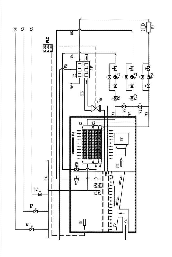
[0013] Such as figure 1 As shown, the present invention has a constant-humidity graded heat exchange drainage and water-wind sensible heat multi-stage utilization relaxation heat setting machine. The inner chamber of the relaxation heat setting machine is provided with a fan Fy, a drying chamber and a heat exchanger, and the outside of the box is equipped with There is a fresh air preheater E4, the air suction port of the fan Fy communicates with the supplementary air port on the cabinet, the air outlet of the fan Fy is aligned with the heat exchanger above, the air outlet above the heat exchanger enters the drying chamber, and the air outlet below the drying chamber There is an air return port and an air exhaust port. The air exhaust port leads to the outside of the box through the exhaust pipe, and the return air port is also connected to the suction port of the fan Fy.

[0014] An exhaust control valve Vk controlled by a PLC controller is installed on the exhaust pipe of th...


PUM


Abstract

The invention relates to a constant humidity type classification heat exchange dewatering and water-wind sensible heat multistage utilization relaxation heat setting machine. A return air inlet and an exhaust outlet are formed in the lower portion of a drying chamber, the exhaust outlet is communicated to the outside of a box body through an exhaust tube, the return air inlet and an air compensation port in the box body are both communicated with a suction outlet of a fan, an air outlet of the fan is aligned to heat exchangers above the fan, the air outlet above the heat exchangers enters into the drying chamber, an inlet of a high pressure heat exchanger is connected with a steam supply main tube, an outlet of the high pressure heat exchanger is connected into an inlet of a middle pressure heat exchanger through a high pressure drain valve, an outlet of the middle pressure heat exchanger is connected into an inlet of a lower pressure heat exchanger through a middle pressure drain valve, an outlet of the low pressure heat exchanger is connected into a condensate pump through a low pressure drain valve, an outlet of the condensate pump is connected into a new wind preheater, a preheating air outlet of the new wind preheater is connected into the air compensation port of the relaxation setting machine, and exhaust and low pressure condensate water of the relaxation setting machine are respectively connected into the new wind preheater to achieve indirect heat exchange with new wind. The setting machine can achieve sufficient utilization of waste heat of the exhaust and the condensate water, and is high in heat efficiency.

Description

technical field [0001] The invention relates to a relaxation heat setting machine, in particular to a constant humidity type relaxation heat setting machine for graded heat exchange, drainage and water wind sensible heat multi-stage utilization. Background technique [0002] The post-treatment of polyester staple fiber often uses a relaxation heat setting machine. The inner chamber of the relaxation heat setting machine is equipped with a fan, a heat exchanger and a drying room for drying the product. The air outlets are connected, and the air outlet of the fan is aligned with the heat exchanger above. Outside the body, a manual control valve is installed on the exhaust pipe, and the air return port is also connected with the suction port of the fan. The fresh air entering the box from the supplementary air inlet is mixed with the return air, and then blown to the heat exchanger by the fan. The heat exchanger heats it into hot air, and the hot air enters the drying chamber ...

Claims


Application Information

Patent Timeline
IPC IPC(8): D02J13/00F26B21/00
Inventor 杨晓辉袁杰周程聂鹏建
Owner YIHENG ENERGY SAVING TECH JIANGSU
Learn More