High-blast-temperature combinative heat exchange system of blast furnace

A heat exchange system and air temperature technology, applied in blast furnaces, blast furnace details, blast furnace parts, etc., can solve the problems of high equipment operating costs, unsatisfactory effects, and high equipment investment

Inactive Publication Date: 2013-04-17
JIANGXI KAISITONG ENVIRONMENTAL PROTECTION EQUIP
View PDF3 Cites 2 Cited by
  • Summary
  • Abstract
  • Description
  • Claims
  • Application Information

AI Technical Summary

Problems solved by technology

However, the effect of the existing technical solutions is not ideal. In order to improve the preheating effect of the system, all the flue gas from the hot blast stove must be introduced into the air mixing chamber, and mixed with the combustion products of about 1100 ° C of the front combustion furnace to form a 500~ The mixed flue gas at 550°C flows into the gas spoiler heat exchanger and the air spoiler heat exchanger respectively to preheat the air and gas to 250-300°C, because the spoiler heat exchanger requires high heat transfer Due to the low temperature difference, the heat exchange efficiency is low. In order to meet the corresponding heat exchange requirements, the volume of the equipment needs to be large enough, the metal consumption is large, and the equipment investment is high; the same as the front burner burns cold air and cold gas. To achieve a higher exhaust gas temperature requires burning a large amount of gas, which makes the operating cost of the equipment high

Method used


Image

  • High-blast-temperature combinative heat exchange system of blast furnace

Examples


Embodiment Construction

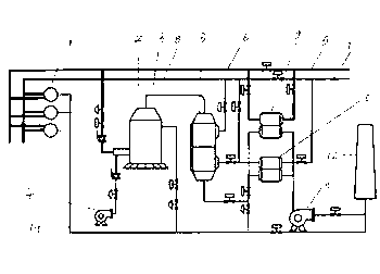
[0005] control figure 1 It can be seen that a blast furnace high air temperature combined heat exchange system includes a hot blast stove 1, a front combustion furnace 2, an air spoiler heat exchanger 3, a blower 4, a cold gas main pipe 5, a hot gas main pipe 6, and a cold air main pipe 7 , hot air main pipe 8, gas heat pipe heat exchanger 9, air heat pipe heat exchanger 10, induced draft fan 11 and chimney 12, said blower 4 and hot gas main pipe 6 are respectively connected to the pre-combustion furnace 2 through the control valve, and the cold gas A control valve is provided between the main pipe 5 and the hot gas main pipe 6, and a control valve is provided between the cold air main pipe 7 and the hot air main pipe 8. The cold gas main pipe 5 is connected to one end of the gas heat pipe heat exchanger 9 through the control valve, and the gas heat pipe is exchanged. The other end of the heater 9 is connected to the hot gas main pipe 6 through the control valve, the cold air ...


PUM


Abstract

The invention provides a high-blast-temperature combinative heat exchange system of a blast furnace, which comprises a hot-blast furnace, a front combustion furnace, an air turbolator heat exchanger, a blast blower, a cold coal gas header pipe, a hot coal gas header pipe, a cold air header pipe, a hot air header pipe, a coal gas heat pipe exchanger, an air heat pipe exchanger, a draught fan and a chimney, wherein the blast blower and the hot coal gas header pipe are respectively communicated with the front combustion furnace by control valves; a control valve is arranged between the cold coal gas header pipe and the hot coal gas header pipe; a control valve is arranged between the cold air header pipe and the hot air header pipe; the cold coal gas header pipe is connected with one end of the coal gas heat pipe exchanger by a control valve; the other end of the coal gas heat pipe exchanger is connected with the hot coal gas header pipe by a control valve; the cold air header pipe is connected with one end of the air heat pipe exchanger by a control valve; and the other end of the air heat pipe exchanger is respectively connected with the hot air header pipe and the air turbolator heat exchanger by control valves. The high-blast-temperature combinative heat exchange system of the blast furnace has the advantages of small equipment size, few metal consumption, low manufacturing cost, low running cost and the like.

Description

technical field [0001] The invention relates to a heat exchange device used in steelmaking or ironmaking, and belongs to the technical field of iron and steel smelting equipment. Background technique [0002] Among the existing iron and steel production equipment, there is a hot blast stove heat exchange device, which mainly consists of a hot blast stove, a gas spoiler heat exchanger, an air spoiler heat exchanger, a front combustion furnace, a mixed air chamber, a hot air blower, Blower and cold air pipe, cold gas main pipe, chimney and proper pipelines and valves, etc. The air outlet of the blower is divided into three ways after passing through the cold air pipe: the first way is connected to the front burner through the valve, and can be used for the front burner. The combustion-supporting air is directly provided; the second route is connected to the hot blast stove through the valve, which can directly provide combustion-supporting air to the hot blast stove; the third...

Claims


Application Information

Patent Timeline
Patent Type & Authority Applications(China)
IPC IPC(8): C21B9/10
Inventor 许永贵李立升
Owner JIANGXI KAISITONG ENVIRONMENTAL PROTECTION EQUIP
Why Eureka
Try Eureka