Fuel tank and engine

A fuel tank and fuel technology, applied in the direction of engine components, machines/engines, liquid fuel feeders, etc., can solve the problems of unsatisfactory liquid fuel inflow scheme, the configuration of the upper end that cannot be piped, and the vicinity of the center.

Inactive Publication Date: 2013-03-06
FUJI JUKOGYO KK
View PDF9 Cites 2 Cited by
  • Summary
  • Abstract
  • Description
  • Claims
  • Application Information

AI Technical Summary

Problems solved by technology

[0010] However, in the techniques described in the aforementioned Patent Documents 1 to 3, the upper end of the fuel vapor discharge pipe cannot be disposed at a position higher than the fuel inlet.
In addition, if the oil filling port is not arranged near the center of the fuel tank body, the upper end of the pipe cannot be arranged near the center of the fuel tank.
[0011] Therefore, in the conventional structure in which the upper end of the fuel vapor discharge pipe is disposed in the fuel inlet, the inflow of liquid fuel may not be ideal.

Method used


Image

  • Fuel tank and engine
  • Fuel tank and engine
  • Fuel tank and engine

Examples


no. 1 approach

[0089] Next, a first embodiment of a fuel tank and an engine to which the present invention is applied will be described.

[0090] The fuel tank and the engine of the first embodiment can be installed in, for example, a portable small engine-driven generator.

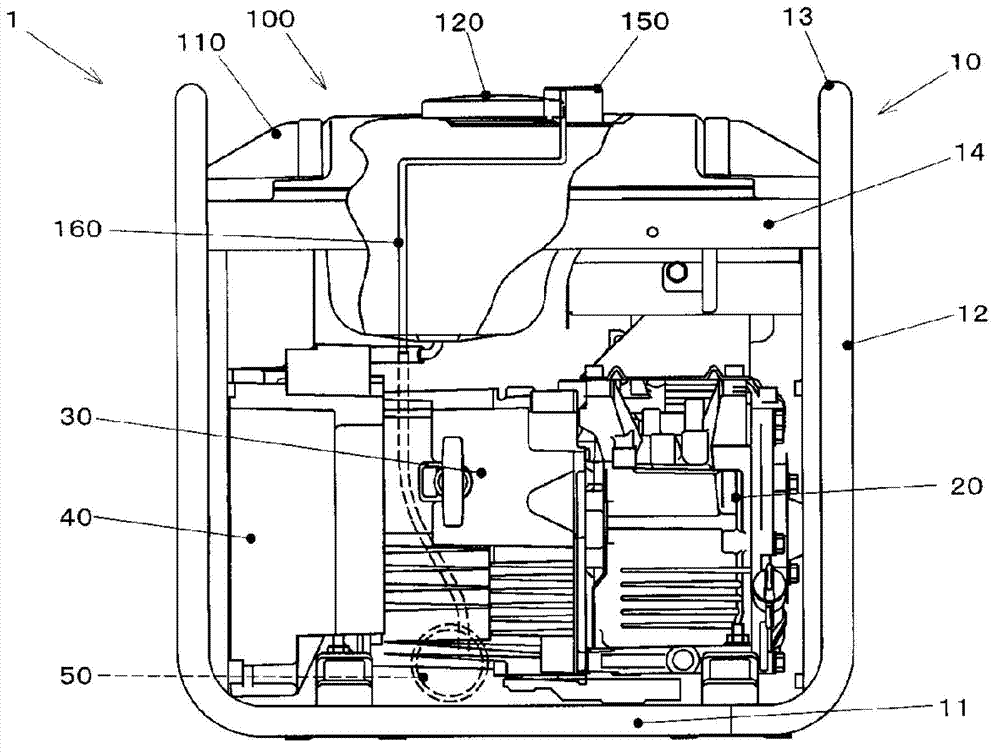
[0091] figure 1 It is a partial cross-sectional side view of an engine-driven generator having the fuel tank and the engine of the first embodiment.

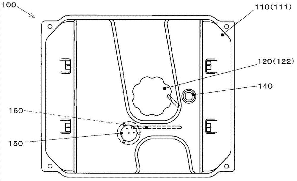
[0092] The engine-driven generator 1 has a frame 10, an engine 20, a recoil starter 30, a blower cover 40, a generator (not shown), a tank 50, a fuel tank 100, and the like.

[0093] The frame 10 is formed, for example, by bending a steel pipe as a base on which the above-mentioned components are mounted.

[0094] From the crankshaft direction (crank axis direction) of the engine 20 ( figure 1 The frame 10 is constituted by both end portions of a pair of lower portions 11 arranged horizontally and parallel in the left-right direction of the paper, and the upper end por...

no. 2 approach

[0149] Next, a second embodiment of the fuel tank using the present invention will be described.

[0150] In addition, the same code|symbol is attached|subjected to the part which is substantially the same as the above-mentioned 1st Embodiment, and description is abbreviate|omitted, and a different point is mainly demonstrated.

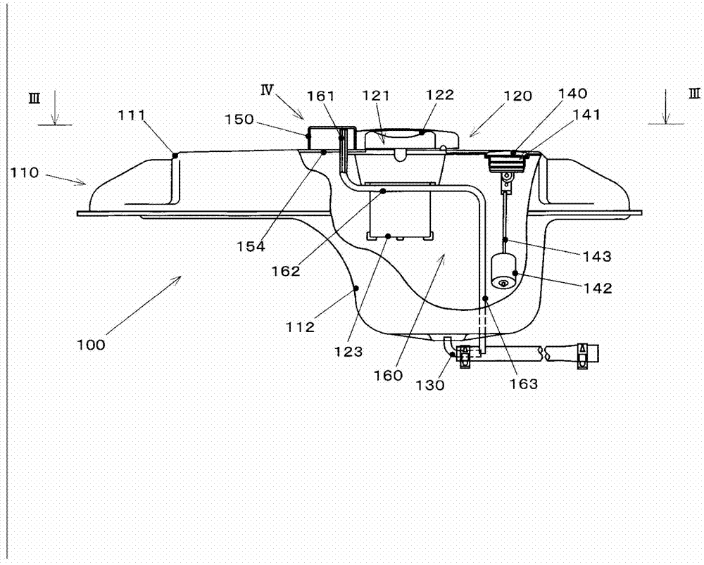
[0151] The fuel tank of the second embodiment is provided with a detachable fuel vapor recovery chamber 250 described below instead of the fuel vapor recovery chamber 150 of the first embodiment.

[0152] Image 6 It is an enlarged cross-sectional view of the fuel vapor recovery chamber 250 of the fuel tank of the second embodiment, showing a state in which the fuel vapor recovery chamber is removed.

[0153] Figure 7 It is an enlarged cross-sectional view of the fuel vapor recovery chamber 250 of the fuel tank of the second embodiment, showing a state in which the fuel vapor recovery chamber is installed.

[0154] The fuel vapor recovery chamber ...


PUM


Abstract

The present invention provides a fuel tank and an engine for reducing flow of the liquid fuel flowed to afuel vapor discharge pipe. A fuel tank (100) comprises a fuel tank body (110) for storingfuels, a fuel feeding inlet (120) which is formed on the upper surface of the fuel tank body, a fuel vapor recovery room (150) which is formed by protruding upward from the upper surface of the fuel tank body and different parts at the fuel inlet and is communicated with the inside of the fuel tank body, and a fuel vapor discharge pipe (160) for which the upper end is arranged in the fuel vapor recovery room, and at least part of the pipe passes through the interior of the fuel tank body so as to connect to the outside, and can discharge the fuel vapor which flows to the fuel vapor recovery room from the fuel tank body to the outside, wherein the upper end part of the fuel vapor discharge pipe is arranged at a position which is higher than the fuel feeding inlet.

Description

technical field [0001] The present invention relates to a fuel tank and an engine, and in particular, relates to a fuel tank and an engine that reduce the flow of liquid fuel into a fuel vapor discharge pipe. Background technique [0002] In an engine using a volatile liquid fuel such as gasoline, it is necessary to reduce the amount of fuel vapor generated by evaporation of the fuel in the fuel tank to be discharged to the outside. [0003] Conventionally, as a technique for treating fuel vapor exhausted from a fuel tank, a canister containing HC adsorbents such as activated carbon is known in a tank, and the fuel vapor is temporarily adsorbed by the activated carbon and burned in the combustion chamber while the engine is running. processing technology. [0004] As the prior art related to this kind of fuel vapor treatment, for example, in Patent Documents 1 to 3, there is disclosed such a technology that, in order to discharge fuel vapor to the outside of the fuel tank, ...

Claims


Application Information

Patent Timeline
IPC IPC(8): F02M37/00F02M25/08
Inventor 铃木操
Owner FUJI JUKOGYO KK
Why Eureka
Try Eureka