
Thin film transistor and manufacturing method thereof

A technology for thin film transistors and a manufacturing method, which is applied to transistors, semiconductor/solid-state device manufacturing, semiconductor devices, etc., can solve the problems of reducing the quality of thin film transistors, affecting the electrical properties of thin film transistors, and damage to oxide semiconductor layers, and shortening production time. , The effect of reducing production cost and improving quality

Active Publication Date: 2013-01-16
TCL CHINA STAR OPTOELECTRONICS TECH CO LTD
View PDF5 Cites 6 Cited by
  • Summary
  • Abstract
  • Description
  • Claims
  • Application Information

AI Technical Summary

Problems solved by technology

[0004] The thin film transistor substrate generally includes a glass substrate and a thin film transistor formed on the glass substrate. The thin film transistor mainly has three structures, namely a co-planar structure, an island-stop structure and a backside structure. Channel (BCE) structure, while the existing oxide thin film transistors are mainly based on the coplanar structure and the etch stop layer structure, because the back channel structure will cause damage to the oxide semiconductor layer during the process and affect its electrical properties.
[0005] see figure 1 , is a structural schematic diagram of an existing back channel thin film transistor formed on a glass substrate 100 through five photomask processes, which includes: a gate 101 formed on the glass substrate 100, a gate insulating layer 103 formed on the The oxide semiconductor layer 105 on the gate insulating layer 103 and the source / drain electrodes 107 formed on the oxide semiconductor layer 105, the oxide semiconductor layer 105 contains zinc oxide (ZnO x ), tin oxide (SnO x ), indium oxide (InO x ) and gallium oxide (GaO x ), which is generally selected from Indium Gallium Zinc Oxide (IGZO); the source / drain 107 is generally formed on the oxide semiconductor layer 105 by a sputtering (sputtering) process in order to form aluminum (Al ) layer and molybdenum (Mo) layer, and then formed by processes such as photoresist material coating, exposure, development, etching and removal of photoresist material. The etching process is required when processing the aluminum layer. The etching solution is generally phosphoric acid (H 3 PO 4 ) and nitric acid (HNO 3 ), and the mixed acid of phosphoric acid and nitric acid will react with the oxide semiconductor layer 105, and cause the oxide semiconductor layer 105 to be etched, thereby affecting the electrical properties of the thin film transistor and reducing the quality of the thin film transistor

Method used


Image

  • Thin film transistor and manufacturing method thereof
  • Thin film transistor and manufacturing method thereof
  • Thin film transistor and manufacturing method thereof

Examples


Embodiment Construction

[0049] In order to further illustrate the technical means adopted by the present invention and its effects, the following describes in detail in conjunction with preferred embodiments of the present invention and accompanying drawings.

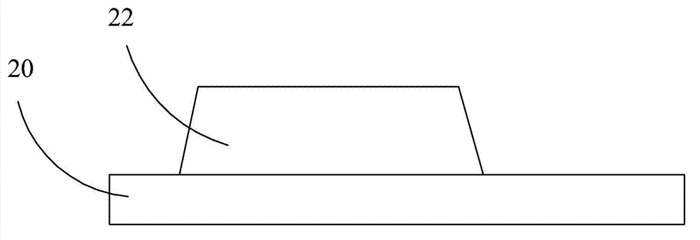
[0050] see Figure 2 to Figure 11 , the invention provides a method for manufacturing a thin film transistor, comprising the following steps:

[0051] Step 1, providing a substrate 20 .

[0052]The substrate 20 is a transparent substrate, preferably a glass or plastic substrate.

[0053] Step 2, forming a first metal layer 22 on the substrate 20, and forming a gate through a photomask process.

[0054] The first metal layer 22 is copper (Cu), aluminum (Al), molybdenum (Mo), titanium (Ti) or a stacked structure thereof.

[0055] Step 3, forming a gate insulating layer 24 on the gate.

[0056] The gate insulating layer 24 is silicon oxide (SiO x ) or silicon nitride (SiN x ) layer formed on the first metal layer 22 by chemical vapor deposi...


PUM

PropertyMeasurementUnit
thicknessaaaaaaaaaa

Abstract

The invention provides a thin film transistor and a manufacturing method thereof. The method includes following steps: step 1, providing a substrate; step 2, forming a first metal layer on the substrate, and forming a grid through photomask process; step 3, forming a grid insulating layer on the grid; step 4, forming an oxide semiconductor layer on the grid insulating layer, and forming a second metal layer on the oxide semiconductor layer, wherein the second metal layer comprises a titanium layer formed on the oxide semiconductor layer and a copper layer formed on the titanium layer, and forming a data line and a source / drain electrode through the photomask process; and step 5, forming a transparent conductive layer on the second metal layer, patterning the transparent conductive layer through the photomask process, and then obtaining the thin film transistor.

Description

technical field [0001] The invention relates to the technical field of flat panel display devices, in particular to a method for manufacturing a thin film transistor and the manufactured thin film transistor. Background technique [0002] A liquid crystal display (LCD, Liquid Crystal Display) has many advantages such as a thin body, power saving, and no radiation, and has been widely used. Most of the liquid crystal display devices currently on the market are backlight liquid crystal display devices, which include a liquid crystal display panel and a backlight module. The working principle of the liquid crystal display panel is to place liquid crystal molecules between two parallel glass substrates, and control the liquid crystal molecules to change direction through whether the glass substrates are energized or not, and refract the light from the backlight module to produce a picture. [0003] Usually, the liquid crystal display panel consists of a color filter (CF, Color ...

Claims


Application Information

Patent Timeline
Patent Type & Authority Applications(China)
IPC IPC(8): H01L21/77H01L29/786
CPCH01L29/7869H01L29/66969
Inventor 郑扬霖萧祥志
Owner TCL CHINA STAR OPTOELECTRONICS TECH CO LTD
Learn More