
Arc striking pulse peak current control electric welding machine and control method thereof

A peak current control and peak current technology, which is applied in arc welding equipment, manufacturing tools, welding equipment, etc., can solve problems affecting the safety of power supply equipment, overcurrent impact, and easy damage, so as to eliminate the sticking phenomenon of welding rods and reduce Inrush current and the effect of eliminating overshoot current

Active Publication Date: 2015-04-01
刘裕国
View PDF5 Cites 1 Cited by
  • Summary
  • Abstract
  • Description
  • Claims
  • Application Information

AI Technical Summary

Problems solved by technology

[0008] The analysis is as follows: Usually, when the thyristor or high-frequency inverter welding power supply is in the constant current working state, the thyristor is in full conduction or the high-frequency inverter switching tube PWM is adjusted to the widest range when it is no-load, and the feedback sampling adjustment lags behind. At the moment of short circuit for a period of time (starting from the first wave), the output voltage is the maximum value, and the output power is the maximum at this time! Over-current impact occurs, (page 62 of "Principles and Design of Inverter Welding" edited by Zhang Guangxian) At this time, the welding rod is easy to stick, and at the same time, it will pose a threat to the power device and be easily damaged
At the same time, the sudden change of the transformer from the minimum power value to the maximum power value may cause serious consequences such as magnetic bias, saturation and fragmentation of amorphous materials! Affect the safety of power equipment
This is also the root cause of the higher failure rate of contact arc welding power supplies than non-contact arc welding power supplies

Method used

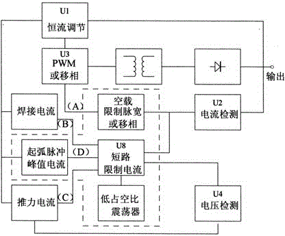
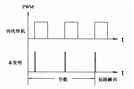

Image

  • Arc striking pulse peak current control electric welding machine and control method thereof
  • Arc striking pulse peak current control electric welding machine and control method thereof
  • Arc striking pulse peak current control electric welding machine and control method thereof

Examples


Embodiment approach

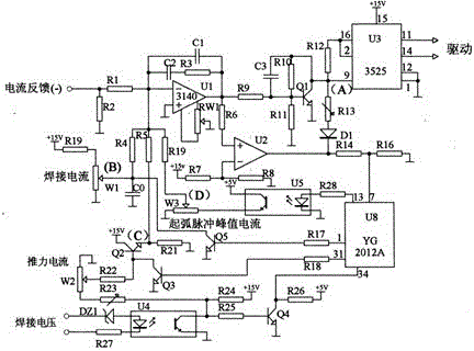
[0037] circuit such as figure 2 As shown, it is a voltage type PWM control circuit type.

[0038] The analysis is as follows: Phase 1: (unloaded)

[0039] There is no welding current at no-load, the given welding current and thrust current are positive values ​​and sent to the regulator U1, U1 outputs the minimum value at this time, Q1 is turned off, U3 (3525) is a voltage-type pulse width modulation integrated circuit, the ninth The pin voltage determines the output pulse width, and drives the power switch device to achieve adjustable output power. The 9th pin is the maximum value of the output at this time!

[0040] The current sampling circuit does not send a signal to U2 to form a current threshold comparison circuit, U2 outputs a low level, R13 will pull down the potential of the 9th pin of U3 (3525) (ie point A) through D1, and adjust the voltage of R13 and U3 pin 9 Clamped at the voltage value with the smallest output pulse width. Generally, the no-load output pulse...


PUM


Abstract

The invention belongs to the field of electric welding and particularly relates to an arc striking pulse peak current control electric welding machine and a control method thereof. The electric welding machine applies a low-frequency low-duty-ratio pulse current during short circuit, and an arc striking pulse peak current of the low-frequency low-duty-ratio pulse current ranges from a 30A welding current to a triplex welding current. Therefore, the arc striking pulse peak current can be higher than the welding current during the low welding current, and arc striking is facilitated; and the arc striking pulse peak current can be lower than the welding current during the high welding current, a short-circuit limit output circuit is cut off after arc striking in welding is successful, the welding current slowly rises from the minimum current to the welding current, and the striking current can be reduced by the means.

Description

technical field [0001] The invention belongs to the field of electric welding, and in particular relates to an electric welding machine controlled by an arcing pulse peak current and a control method thereof. Background technique [0002] The steady state current Iwd of the traditional electrode arc welding is designed to be larger than the welding current If from no-load to short circuit, and the ratio range of the steady state current Iwd to the welding current If is: 1.25<Iwd / If<2, [0003] The increased current is the arc ignition current. After the electrode is lifted, the arc is ignited, and the output current decays to the welding current to complete the arc ignition process. The characteristics of arc ignition generally depend on the current peak value and the decay time of arc ignition current. If the peak value of the arc striking current is too small and the arc striking current time is too short, it is not conducive to thermal emission and thermal ionizati...

Claims


Application Information

Patent Timeline
Patent Type & Authority Patents(China)
IPC IPC(8): B23K9/095B23K9/06B23K9/10
Inventor 刘裕国
Owner 刘裕国
Learn More