Electric brake

A technology of electric brakes and brake discs, applied in the direction of brake actuators, gear transmission mechanisms, mechanical equipment, etc., can solve the problems of large volume, cumbersome installation of hydraulic oil pipes, and easy leakage

Active Publication Date: 2012-10-31
CHERY AUTOMOBILE CO LTD
View PDF7 Cites 11 Cited by
  • Summary
  • Abstract
  • Description
  • Claims
  • Application Information

AI Technical Summary

Problems solved by technology

However, the hydraulic brake system has a long braking reaction time, a long braking distance, cumbersome installation of hydraulic oil pipes, easy leakage, and large volume, which is not conducive to the installation and installation on the whole vehicle.

Method used


Image

  • Electric brake
  • Electric brake

Examples


Embodiment Construction

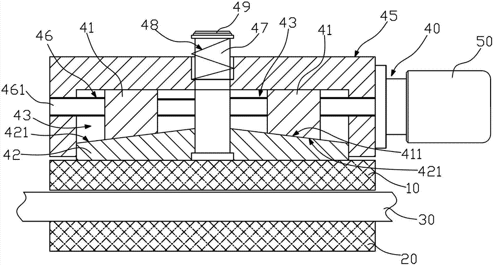
[0008] Such as figure 1 , an electric brake, including a dynamic friction plate 10 and a static friction plate 20, the dynamic and static friction plates 10, 20 are arranged on both sides of the brake disc 30, the dynamic friction plate 10 is fixed on the actuator 40, the actuator 40 is connected to the motor 50 , and the actuator 40 drives the moving friction plate 10 away from or close to the brake disc 30 . The dynamic friction plate 10 is attached to the brake disc 30 to achieve braking. When the dynamic friction plate 10 is far away from the brake disc 30, the brake is released. The electric motor 50 is used to provide power without complicated hydraulic systems, which can simplify the structure, reduce the volume of the brake, and avoid It eliminates a series of problems such as leakage caused by hydraulic drive, and is suitable for vehicle installation.

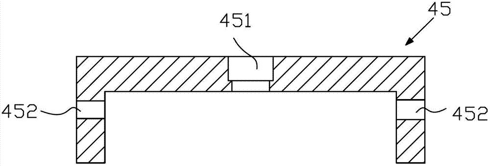
[0009] Such as figure 1 , the actuator 40 includes a housing 45 and a moving block 42 located on the side of the m...


PUM


Abstract

The invention relates to the field of automobile brake systems, in particular to an electric brake including a kinetic friction plate and a static friction plate arranged on two sides of a brake disc, wherein the kinetic friction plate is fixed on an actuating mechanism, the actuating mechanism is connected with an electromotor, the kinetic friction plate is driven by the actuating mechanism to get far away from or close to the brake disc, the kinetic friction plate is clung onto the brake disc to realize brake, and the brake is released when the kinetic friction plate gets far away from the brake disc. The electromotor is adopted for providing power, and a complicated hydraulic system is not required, so that the structure can be simplified, the volume of the brake can be reduced, leakage and a series of problems caused by hydraulic drive can be avoided, and the electric brake is suitable for entire automobile installation.

Description

technical field [0001] The invention relates to the field of automobile brake systems, in particular to electric brakes. Background technique [0002] At present, most vehicle braking systems at home and abroad are still based on hydraulic control of mechanical pressure to achieve the purpose of braking. The hydraulic brake system has the advantages of good linearity and high stability, and can be matched with electronic auxiliary systems such as ABS and EPS, which can be regarded as a very mature technical form. However, the hydraulic brake system has a long braking reaction time and a long braking distance. The hydraulic oil pipe is cumbersome to install, easy to leak, and has a large volume, which is not conducive to the installation and installation on the vehicle. Contents of the invention [0003] The purpose of the present invention is to provide an electric brake with large braking force and small volume. [0004] In order to achieve the above object, the present...

Claims


Application Information

Patent Timeline
IPC IPC(8): F16D65/14F16D121/24
Inventor 江涛
Owner CHERY AUTOMOBILE CO LTD
Why Eureka
Try Eureka