
Method, system and chip test paper for parallel detection on various cardiac markers

A myocardial marker and detection method technology, applied in the field of in vitro immunoassay, can solve the problems of long detection time, long time, and limited development, and achieve the effects of saving detection time, rapid detection response, and improving sensitivity

Inactive Publication Date: 2012-08-15
SHANGHAI LINC BIO SCI
View PDF6 Cites 10 Cited by
  • Summary
  • Abstract
  • Description
  • Claims
  • Application Information

AI Technical Summary

Problems solved by technology

Colloidal gold label technology has played an important role in the field of rapid detection, which has won time for patient diagnosis, and is easy to use, which has won the favor of users; but due to the bottleneck of low detection sensitivity and inability to accurately quantify, it cannot give full play to its potential The demand for rapid diagnosis cannot compete with precise chemiluminescence and other technologies
Technology platforms such as chemiluminescence and time-resolved fluorescence have greatly improved the detection sensitivity, and with the assistance of a fully automatic detection system, the detection error and detection efficiency have been greatly improved; however, due to its relatively long detection time, and the instrument The equipment is relatively large and can only be carried out in the central laboratory. It still takes a long time from sample collection to the doctor getting the test results. At the same time, one test can only get the result of one marker, and it cannot measure multiple biological factors related to the patient at the same time. marker results, thus greatly limiting the full development of this technology platform
With the development of chip technology, technical platforms such as membrane chips, liquid chips, and glass chips have emerged one after another, which can achieve the purpose of synchronous testing of multiple biomarkers for the same sample, saving time and cost for patient testing, and saving samples at the same time. However, the platform technology still has cumbersome experimental reactions and operations that increase the detection error. At the same time, the equipment is relatively large, and it can only be carried out in the central laboratory. It also takes a long time from sample collection to doctors getting the experimental results. time limits its development
Limits further development in the field of immunoassays
Neither can meet the needs of the rapidly developing field of immunization
[0018] In view of this, due to the problems that the current detection method has a long detection time, rapid detection cannot be quantified, and the same detection can only obtain the result of one marker, there is an urgent need for a new detection method that can quickly and accurately detect and can Simultaneously detect the preparation of multiple myocardial markers, and it is also easy to carry and can be used anytime, anywhere

Method used


Image

  • Method, system and chip test paper for parallel detection on various cardiac markers
  • Method, system and chip test paper for parallel detection on various cardiac markers
  • Method, system and chip test paper for parallel detection on various cardiac markers

Examples


Embodiment 1

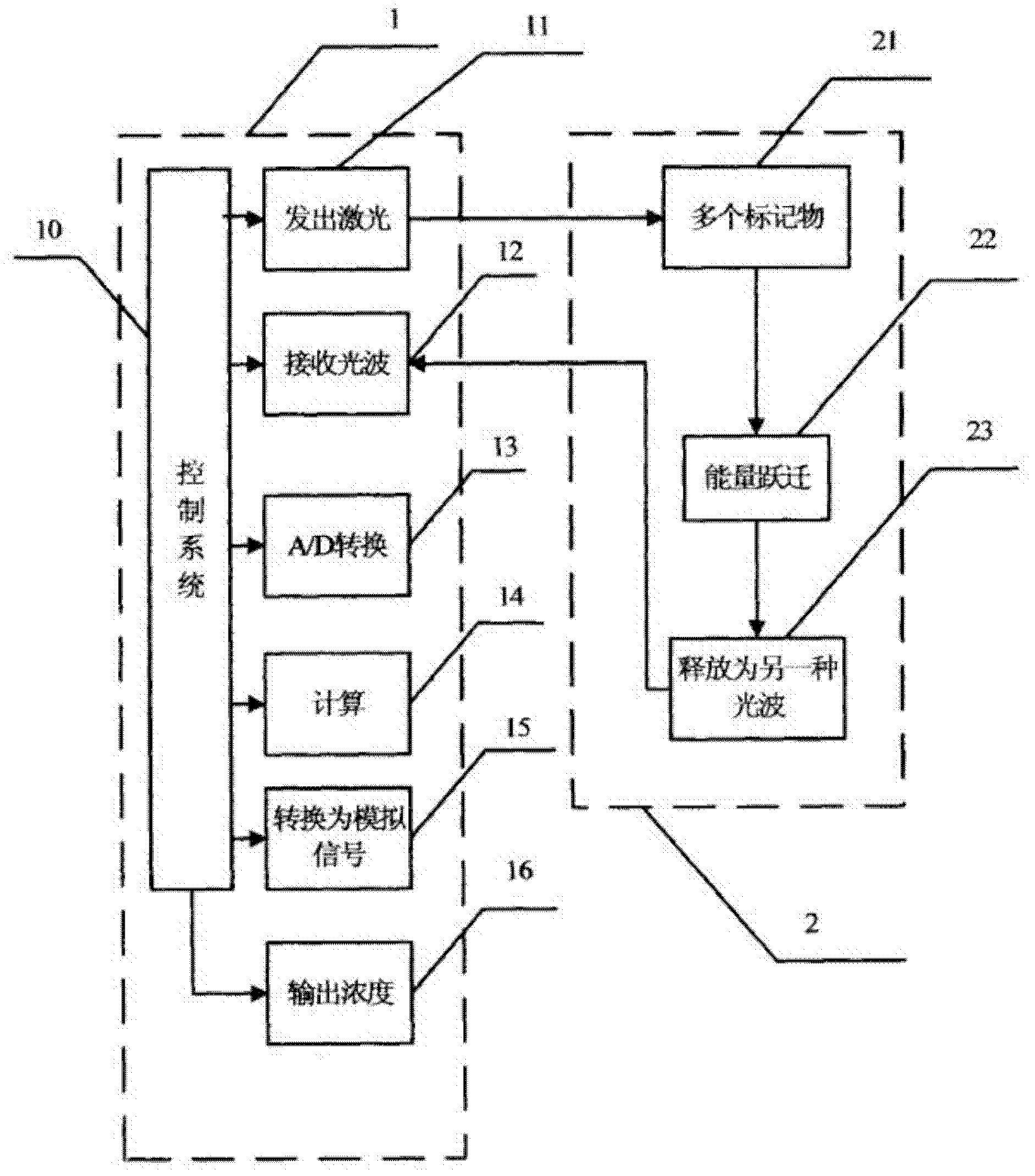
[0056] see figure 1 , the present invention discloses a parallel detection system for multiple myocardial markers, the detection items are common gold standard markers of myocardial: cTNI, cTNT, MYO, CK-MB, BNP, CRP, FABP; the detection system includes fluorescence detection Instrument 1, kit 2. The control system 10 of the detector controls various working states of the detector.

[0057] The laser emitter 11 emits laser light, which simultaneously excites various signal markers 21 in the chip test strip 2 , and these markers undergo energy transition 21 after being excited by the laser light, and then release another mutated light wave or electronic substance 23 .

[0058] At the same time, the signal receiving device 12 of the detector 1 receives the light wave or electron carrier signal 23 released by the signal marker, and converts the signal 23 into a digital signal 13. The magnitude of the signal marker release signal is positively correlated with the value. Then the ...

specific Embodiment

[0079] The implementation mode of the chip test paper detector:

[0080] see Figure 4 As shown, the detector includes: laser 31, filter group 32, optical filter 33, dichroic mirror 38, mirror 35, first objective lens 34, second optical filter 36, second objective lens 37, diaphragm 40 And chip test paper 39, and PMT (photomultiplier tube) components, AMP (signal amplifier) ​​components, converter A / D (signal data converter) components, CD chip, output printing equipment, main board and power supply equipment (not shown in the figure ).

[0081] Detector assembly and testing

[0082] According to the design diagram, connect the optical components in the instrument box in turn, and distribute the power supply and control board, and check the working conditions of each section of lines and components in turn to check whether they meet the requirements. After fully conforming, turn on the main board control program and power supply, and test the working condition of the system...

Embodiment approach

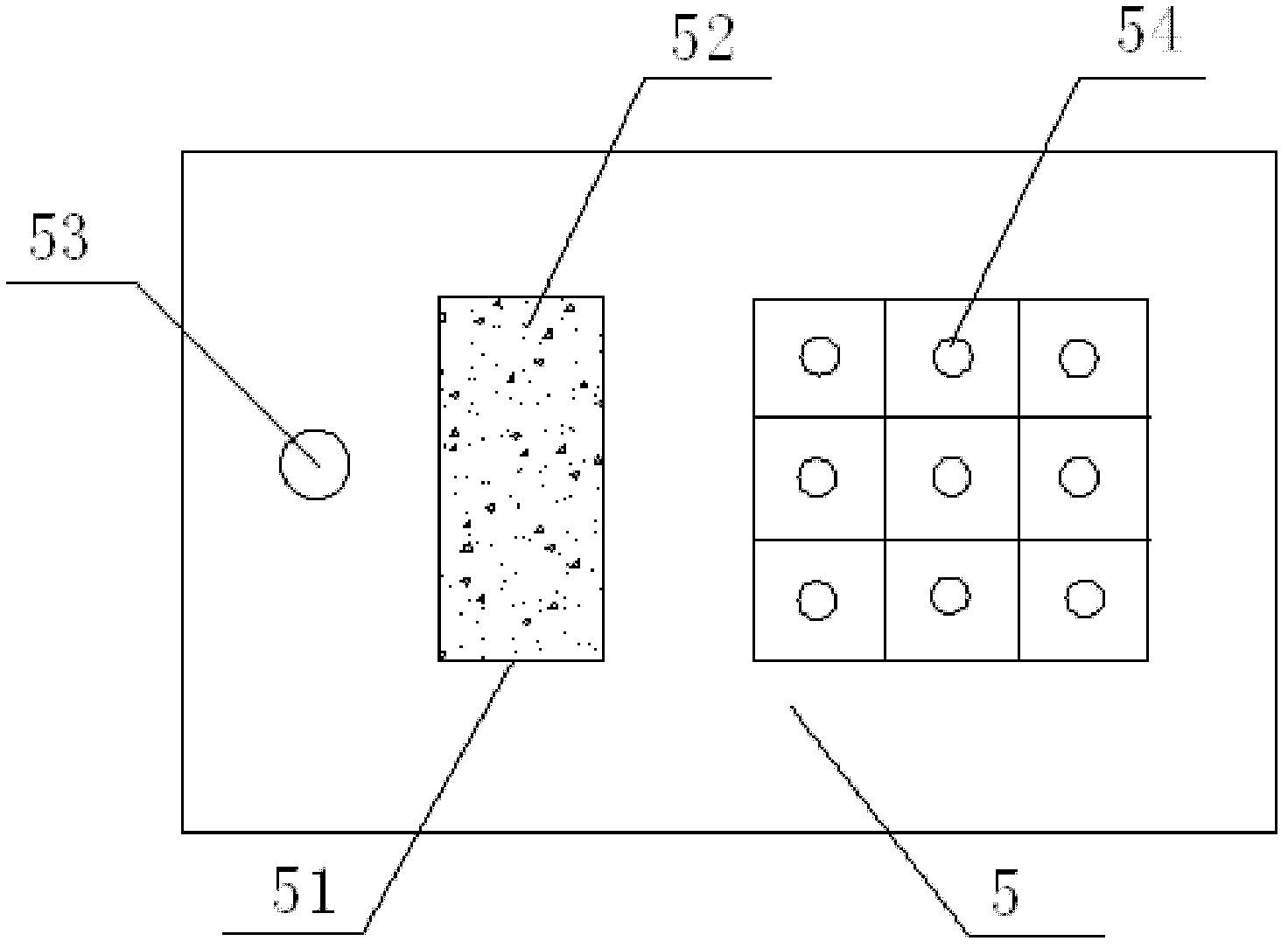
[0087] The material of the chip test paper can be NC film or glass sheet or plastic sheet, etc. The chip dot matrix is ​​5X6 or other arrangements (determined according to the specific product), the spacing is 1mm, the spot diameter is 10um-500um, and the overall width of the test paper is 3-30mm. Length range: 30-100mm. Appearance includes sampling hole, chip irradiation window, sealing card, positioning mark, etc. The internal structure of the chip test paper includes: filter paper, glass fiber where the signal marker ligand is located, ligand lattice (including test points, calibration points and quality control points), etc.

[0088] According to the above design and production test, the chip test paper detector fully meets its advantages of fast, sensitive, quantitative detection, multiple joint inspections, and easy to carry. It is a product with a wide range of applications in the future, which will play a role in promoting the development of clinical testing in the fu...


PUM


Abstract

The invention discloses a method, system and chip test paper for parallel detection on various cardiac markers. The chip test paper is used for detecting a part or all of the cardiac markers including cTNI (cardiac troponin I), cTNT (cardiac troponin T), MYO (myoglobin), CK-MB (isoenzymeof creatine kinase containing M and B subunits), BNP (B-type natriuretic peptide), CRP (C-reactive protein) and FABP (fatty acid-binding protein); the chip test paper comprises a first membrane and a second membrane; a ligand An of each marker is arranged on the first membrane, and a ligand Bn coupled with a signal marker is absorbed on the second membrane; and a detected material forming sandwich detection together with the ligands An and Bn is added from a sampling hole, then under the acting force of percolation or other factors, the detected material moves to be combined with the ligands An and Bn respectively to form a composite array of the first membrane-the ligand An-the detected material-the ligand Bn-the signal marker, which is fixed on the first membrane, the composite array and a capture fiber membrane are assembled simultaneously, and a detection hole is reserved. The method, the system and the chip test paper provided by the invention can be used for detecting the various cardiac markers simultaneously and quantitatively; moreover, the detection sensitivity can be improved, and the detection time is saved.

Description

technical field [0001] The invention belongs to the technical field of in vitro immune analysis, and relates to a parallel detection method for markers, in particular to a parallel detection method for multiple myocardial markers; the invention also relates to a parallel detection system for multiple myocardial markers; meanwhile, the present invention It also relates to a chip test paper for parallel detection of multiple myocardial markers. Background technique [0002] Cardiovascular diseases such as acute myocardial injury, chronic heart failure and atherosclerosis are common diseases that seriously endanger human health. Since the 1950s, the dynamic determination of the activities of some metabolic enzymes has been the gold standard for the diagnosis of acute myocardial infarction (acute myocardial infarction, AMI). However, these enzymes are not unique to the myocardium. They also exist in large quantities in other organs and muscles of the human body. In addition to ...

Claims


Application Information

Patent Timeline
Patent Type & Authority Applications(China)
IPC IPC(8): G01N33/68G01N21/63
CPCG01N33/6893G01N33/74
Inventor 罗朝领茅柳娟
Owner SHANGHAI LINC BIO SCI
Learn More