Power-on current-limiting circuit and application circuit of power-on current-limiting circuit

A technology of current limiting circuit and rectifying circuit, which is applied to emergency protection circuit devices, circuit devices, emergency protection circuit devices for limiting overcurrent/overvoltage, etc. , current waveform asymmetry and other problems, to achieve the effect of adjustable power-on current, good power-on effect, and improved primary impedance

Inactive Publication Date: 2014-07-02
上海寰晟新能源科技有限公司
View PDF4 Cites 0 Cited by
  • Summary
  • Abstract
  • Description
  • Claims
  • Application Information

AI Technical Summary

Problems solved by technology

The problem with the first two methods is: the secondary current impact problem is brought about when the resistance is cut off
The problem with the latter method is that it is only suitable for applications where the load power is less than 200W
[0004] After searching the existing technology, it was found that Zhang Xiangjun et al., "Journal of Electrical Machinery and Control". June 2011. Summarized two traditional soft-start circuits, including the first two methods mentioned above, and proposed "a start-up surge current Suppression circuit", that is, a three-stage inrush current suppression circuit, which can effectively suppress the primary inrush current and the secondary inrush current at start-up, but there is still an inrush current, and the harmonic current impact on the power grid is relatively serious, and the structure is complex. The number of components is large, the control is not easy, the power-on process is uncontrollable, the current waveform is asymmetrical during the power-on process, and the reactive power is large

Method used


Image

  • Power-on current-limiting circuit and application circuit of power-on current-limiting circuit
  • Power-on current-limiting circuit and application circuit of power-on current-limiting circuit
  • Power-on current-limiting circuit and application circuit of power-on current-limiting circuit

Examples


Embodiment 1

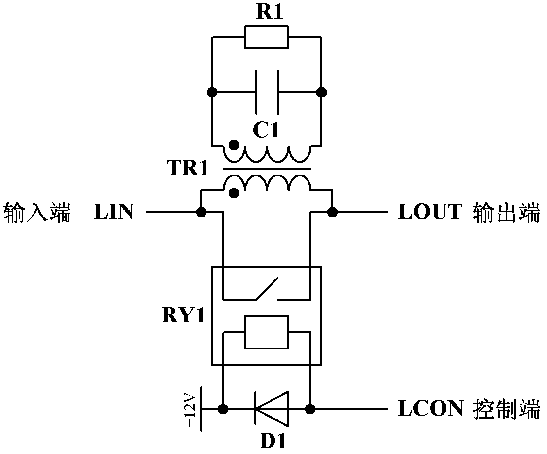
[0021] Such as figure 1 As shown, this embodiment provides a power-on current limiting circuit, the power-on current limiting circuit CLC1 includes: transformer TR1, resonant capacitor C2, resonant resistor R1, relay RY1, power diode D1 and power supply, wherein: power-on limit The input terminal of the current circuit CLC1 is respectively connected to one terminal of the primary side of the transformer TR1 and the positive pole of the output terminal of the relay RY1, and the other terminal of the primary side of the transformer TR1 is connected to the negative pole of the output terminal of the relay RY1 to form the output terminal of the power-on current limiting circuit CLC1, and the resonant capacitor C2 and the resonant resistor R1 are connected across the secondary side of the transformer TR1, the power diode D1 is reversely connected to the input terminal of the relay RY1, the control power supply is respectively connected to the positive pole of the input terminal of t...

Embodiment 2

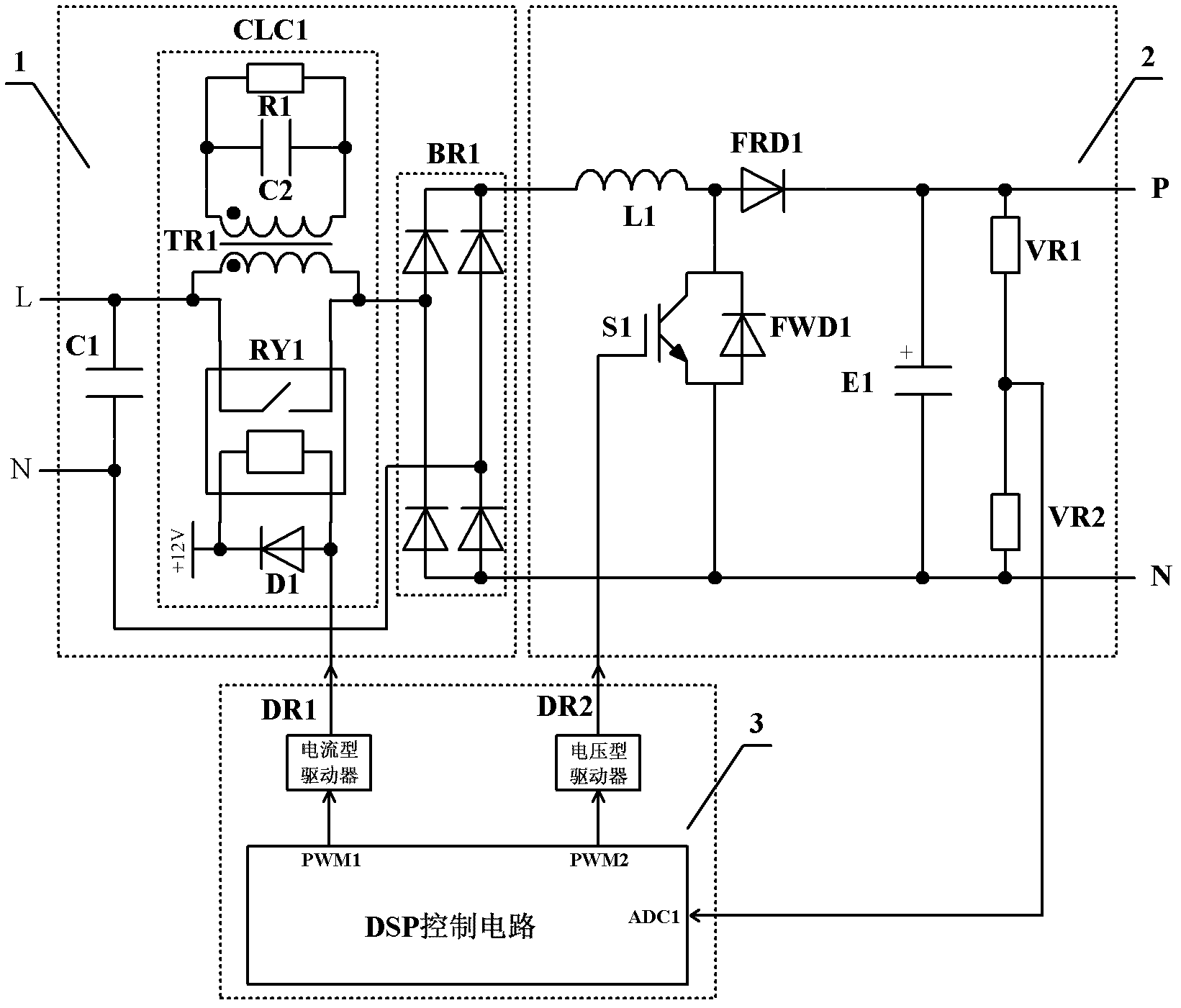
[0024] Such as figure 2 As shown, this embodiment provides a figure 1 The application circuit of the power-on current limiting circuit shown includes: a rectification circuit 1, a boost circuit 2 and a control circuit 3, wherein: the output terminal of the rectification circuit 1 is connected to the input terminal of the boost circuit 2, and the output terminal of the boost circuit 2 The output terminal is connected to the control circuit 3 , the control terminals of the rectification circuit 1 and the boost circuit 2 are connected to the output terminal of the control circuit 3 , and the power-on current limiting circuit CLC1 is connected in series to the AC side of the rectification circuit 1 .

[0025] The rectifier circuit 1 includes: an input filter capacitor C1, a power-on current limiting circuit CLC1 and a rectifier bridge BR1, wherein: the input filter capacitor C1 is connected across the two ends of the single-phase AC power supply, and the input terminal of the pow...

Embodiment 3

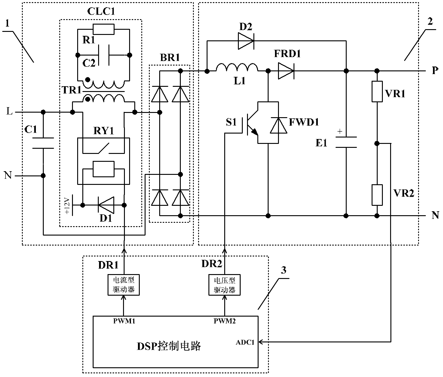
[0036] Such as image 3 As shown, this example involves a figure 1 The difference between the application circuit of the power-on current limiting circuit shown and the circuit schematic diagram of Embodiment 2 is that a power diode, called the second power diode D2, is added to the boost circuit, and the original rectifier circuit 1 The power diode D1 is renamed as the first power diode D1, the anode of the second power diode D2 is connected to the positive pole of the output terminal of the rectifier bridge BR1 and the common terminal of the boost inductor L1, and the cathode of the second power diode D2 is connected to the fast recovery diode FRD1 connected to the cathode.

[0037] The second power diode D2 is HER607.

[0038] The working principle of this embodiment is exactly the same as that of Embodiment 2, and the second power diode D2 can prevent DC voltage pumping during the power-on stage, making the circuit work safer and more reliable.

[0039] Compared with Em...


PUM


Abstract

The invention discloses a power-on current-limiting circuit and an application circuit of the power-on current-limiting circuit. The input end of the power-on current-limiting circuit is connected with one end of the primary side of a transformer and the positive electrode of the output end of a relay respectively, and the other end of the primary side of the transformer is connected with the negative electrode of the output end of the relay so as to form the output end of the power-on current-limiting circuit; a resonant capacitor and a resonant resistor are in bridge connection with the secondary side of the transformer; a first power diode is in reverse connection with the input end of the relay; and the positive electrode of the input end of the relay and the cathode of the first power diode are respectively connected with a control power supply, and the negative electrode of the input end of the relay is connected with the anode of the first power diode so as to form the control terminal of the power-on current-limiting circuit. The power-on current-limiting circuit and the application circuit are simple in structures, are convenient to control, can be matched with a three-phase diode rectifier, a single-phase diode rectifier, a three-phase IGBT (insulated gate bipolar transistor) controlled rectifier and a single-phase IGBT controlled rectifier, and can be laid on an alternating current side or a direct current side and widely applied to all power electronic convertors, the power-on current is adjustable, the power-on effect is good, the current displacement factor is always 1, and the service life of an electrolytic capacitor is long.

Description

technical field [0001] The invention relates to a device in the technical field of power electronic converters, in particular to a power-on current limiting circuit and an application circuit thereof. Background technique [0002] The power electronic conversion device powered by single-phase AC power supply can be used in application fields such as switching power supply, high-power inverter, active power factor corrector (APFC), among them, for high-power power factor corrector (PFC), including single The phase diode does not control the rectifier bridge and boost circuit. For high-power applications, the energy storage capacitor on the output side of the boost circuit has a large capacity, and the initial voltage of the energy storage capacitor is zero. When the single-phase AC power supply is powered on when the energy storage capacitor is at zero voltage, a high-amplitude inrush current will be generated, resulting in adverse results: causing the air switch to operate ...

Claims


Application Information

Patent Timeline
Patent Type & Authority Patents(China)
IPC IPC(8): H02H9/02H02M1/32
Inventor 马红星李华武杨喜军
Owner 上海寰晟新能源科技有限公司
Why Eureka
Try Eureka