Maximum torque per ampere vector control system and control method for position sensor-free internal permanent magnet synchronous motor
A technology of permanent magnet synchronous motor and maximum torque current, which is applied in vector control system, control system, motor generator control, etc., and can solve problems such as poor accuracy of current given value and complicated calculation method
- Summary
- Abstract
- Description
- Claims
- Application Information
AI Technical Summary
Problems solved by technology
Method used
Image
Examples
specific Embodiment approach 1
[0055] Specific implementation mode one: the following combination figure 1 Describe this embodiment, the maximum torque current ratio vector control system of the permanent magnet synchronous motor with built-in position sensor described in this embodiment, it includes a permanent magnet synchronous motor 1, it also includes an inverter 2, a space vector pulse width modulation unit 3. Three-phase-two-phase coordinate transformation unit 4. Stationary-rotating coordinate transformation unit 5. Fourier analysis unit 6. Vector angle adjustment unit 7. Speed regulator 8. Maximum torque-to-current ratio control unit 9. First current Regulator 10, second current regulator 11, rotation-stationary coordinate transformation unit 12 and rotor position and speed observer 13,
[0056] The rotor position and speed observer 13 collects the a-phase stator current i of the permanent magnet synchronous motor 1 a , phase c stator current i c , DC bus voltage u of inverter 2 dc and the swi...
specific Embodiment approach 2
[0059] Specific implementation mode two: the following combination figure 2 Describe this embodiment, this embodiment is based on the control method of the maximum torque current ratio vector control system of the non-position sensor built-in permanent magnet synchronous motor described in the first embodiment: it includes the following steps:
[0060] Step 1: Feedback value i of the q-axis current of the permanent magnet synchronous motor 1 q and the d-axis current feedback value i d Perform Fourier analysis to extract the DC component of the q-axis current and the DC component of the d-axis current;
[0061] Step 2: Average the q-axis current DC component and the d-axis current DC component in one current cycle obtained in step 1, and output them to the vector angle adjustment unit 7;
[0062] Step 3: Calculate the square of the current vector amplitude by the vector angle adjustment unit 7 according to the average value of the q-axis current DC component and the d-axis c...
specific Embodiment approach 3
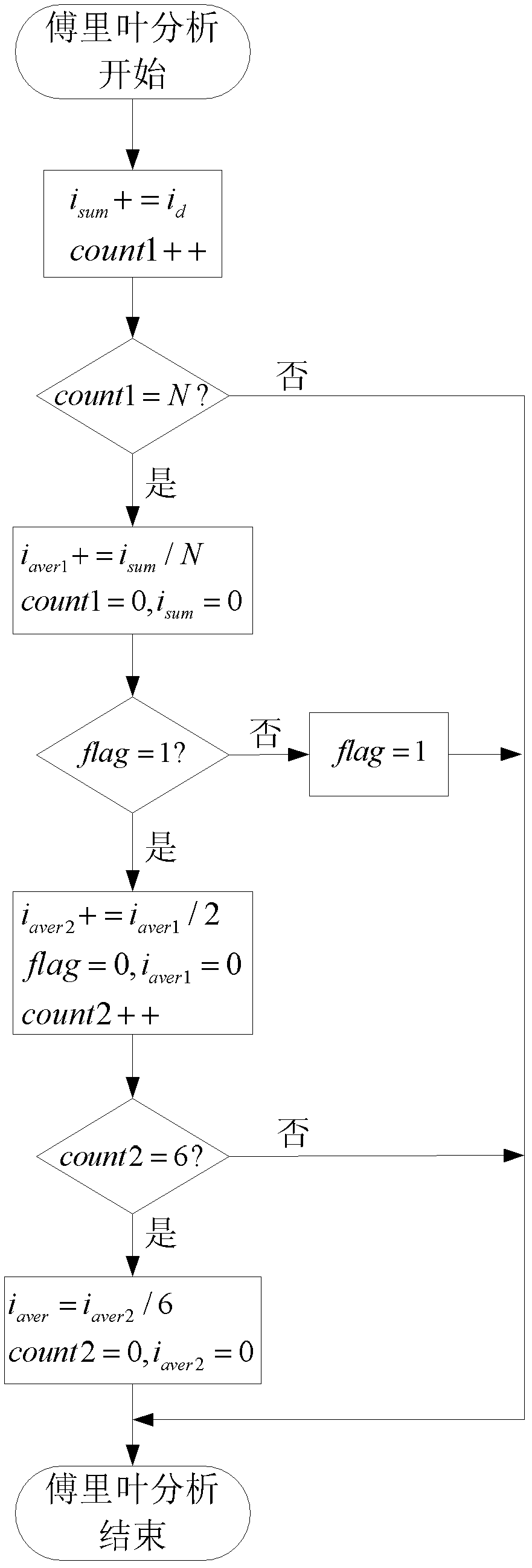
[0065] Specific implementation mode three: the following combination image 3 Describe this embodiment. This embodiment is a further description of Embodiment 2. In the step 1, the q-axis current feedback value i of the permanent magnet synchronous motor 1 q and the d-axis current feedback value i d Perform Fourier analysis to extract the DC component of the q-axis current and the DC component of the d-axis current. The specific method is as follows:
[0066] The acquisition method of the q-axis current DC component is the same as that of the d-axis current DC component. The following takes the acquisition method of the d-axis current DC component as an example to illustrate:
[0067] The Fourier analysis unit 6 collects the d-axis current feedback value i each time d After that, using the current accumulator i sum Accumulate the d-axis current feedback value id, and use the counter count1 to count the number of current acquisitions;
[0068] Determine whether the current ...
PUM
 Abstract
Description
Claims
Application Information
 - R&D
- Intellectual Property
- Life Sciences
- Materials
- Tech Scout
- Unparalleled Data Quality
- Higher Quality Content
- 60% Fewer Hallucinations
Browse by: Latest US Patents, China's latest patents, Technical Efficacy Thesaurus, Application Domain, Technology Topic, Popular Technical Reports.
© 2025 PatSnap. All rights reserved.Legal|Privacy policy|Modern Slavery Act Transparency Statement|Sitemap|About US| Contact US: help@patsnap.com


