Cam grinding device

A cam and grinding technology, which is applied in the direction of grinding/polishing equipment, turning equipment, cams, etc., can solve the problems of increasing grinding time, inaccurate grinding of a single cam, and inaccurate grinding, so as to reduce the grinding time , The effect of reducing the grinding cost

Inactive Publication Date: 2012-05-16
MAHLE INT GMBH
View PDF4 Cites 5 Cited by
  • Summary
  • Abstract
  • Description
  • Claims
  • Application Information

AI Technical Summary

Problems solved by technology

However, it is disadvantageous in this regard that such a metal holding mandrel can flex elastically during grinding of the cams, which leads to inaccurate grinding of the individual cams
At the same time, this metal holding arbor is subject to wear that cannot be underestimated and therefore has to be replaced regularly, which likewise increases the grinding costs per cam to be ground
In addition, since each holding mandrel is usually only capable of supporting at most four cams at the same time, and each cam requires, for example, 15 seconds of grinding time, a total of 60 seconds is required to grind the four cams
Due to the bending of the metal holding mandrel and the associated or attendant grinding inaccuracies, it is only possible to grind four cams simultaneously when grinding with relatively low grinding pressures, with the resultant increase in grinding time

Method used


Image

  • Cam grinding device
  • Cam grinding device

Examples


Embodiment Construction

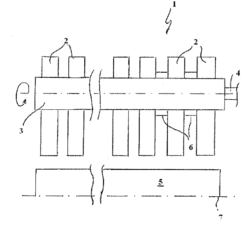
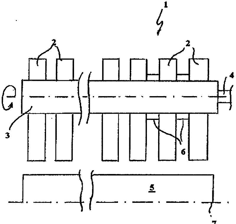
[0012] Such as figure 1 As shown in , the device 1 according to the invention for grinding a cam 2 has a holding mandrel 3 on which the cam 2 is non-rotatably fixed during the grinding operation. According to the invention, such a holding mandrel 3 is preferably formed, at least in some regions, predominantly from ceramics, in particular technical ceramics. In this case, the holding spindle 3 is connected in a non-rotatable manner to a shaft 4 of a drive device (not shown). According to the invention, since the retaining mandrel 3 is formed of ceramic, said mandrel has a high modulus of elasticity and a high strength associated therewith. This makes it possible to grind a plurality of cams 2 , preferably eg eight cams 2 , simultaneously by pressing the cams 2 against the grinding elements 5 of the device 1 . The grinding element 5 itself typically has a rapidly rotating grinding body which is pressed against the cam 2 clamped on the holding arbor 3 . It goes without saying ...


PUM


Abstract

The present invention relates to a device (1) for grinding cams (2) for a camshaft, comprising at least one retaining mandrel (3), on which the cams (2) are non-rotatably fixed during the grinding process, wherein the at least one retaining mandrel (3) is at least in some regions made of ceramic material. Due to the high modulus of elasticity and the high strength of the ceramic retaining mandrel (3), the grinding costs can be substantially reduced.

Description

technical field [0001] The invention relates to a device for grinding cams of a camshaft and also to a method for grinding cams of a camshaft using such a grinding device. Background technique [0002] Cams for camshafts, in particular camshafts for internal combustion engines, generally have to be ground so that the associated valves can be driven as precisely and accurately as possible. Until now, this has been achieved with so-called camshaft grinding machines, in which the cams to be ground are clamped on metal holding mandrels (eg hydraulic expansion mandrels) and thus it is possible to grind several camshafts arranged axially parallel to each other cam. A disadvantage in this regard, however, is that such a metal holding mandrel can flex elastically during grinding of the cams, which leads to inaccurate grinding of the individual cams. At the same time, such metal holding spindles are subject to wear that cannot be underestimated and therefore have to be replaced reg...

Claims


Application Information

Patent Timeline
Patent Type & Authority Applications(China)
IPC IPC(8): B24B19/12B24B41/06
CPCB23P11/025B23B31/40B23B2226/18B23B2270/20B23P2700/02B24B19/12B23B31/1179B24B41/067B23Q3/061Y10T29/511Y10T29/49995
Inventor 罗兰·沙赫雷尔
Owner MAHLE INT GMBH
Why Eureka
Try Eureka