
Testing system for researching flow boiling heat transfer character and pressure drop character of cryogenic fluid

A technology of boiling heat transfer and pressure drop characteristics, applied in low temperature engineering and low temperature field, can solve the problems of high overall system integration, unavailability, limited capacity of evaporation pressure, etc., to simplify complexity, reduce test cost and improve utilization efficiency effect

Inactive Publication Date: 2012-05-02
SHANGHAI JIAO TONG UNIV
View PDF4 Cites 33 Cited by
  • Summary
  • Abstract
  • Description
  • Claims
  • Application Information

AI Technical Summary

Problems solved by technology

The above-mentioned test systems all have the following deficiencies: 1) The power source is set separately in the system, the system is complicated and the investment is large; 2) The cryopump or high-pressure nitrogen is used as the power source, and the ability to adjust the evaporation pressure in a wide range is limited; 3) The overall system The integration is high, and the application of the test platform is relatively single, which is not suitable for testing a variety of low-temperature fluids; 4) It is difficult to replace the specific heat exchange equipment to be tested in the test system; 5) When there is a fluid leak in the system, there is no emergency treatment device, Not suitable for flammable and explosive cryogenic fluid tests
These deficiencies greatly limit the experimental and theoretical research on the flow boiling heat transfer characteristics and pressure drop characteristics of cryogenic fluids, and also affect the research and application of related low temperature heat exchange equipment.

Method used


Image

  • Testing system for researching flow boiling heat transfer character and pressure drop character of cryogenic fluid
  • Testing system for researching flow boiling heat transfer character and pressure drop character of cryogenic fluid

Examples


Embodiment Construction

[0020] The specific implementation of the present invention will be further described below in conjunction with the accompanying drawings.

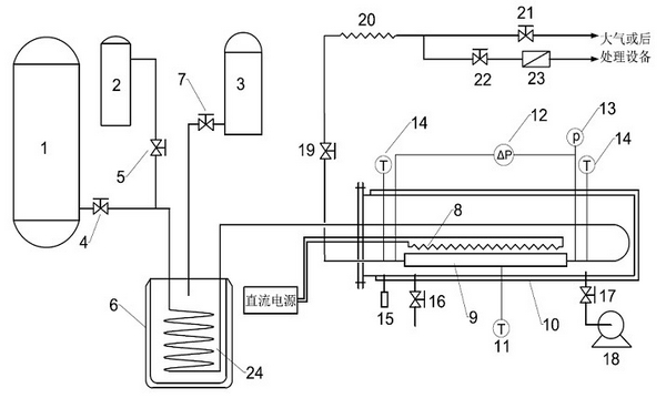
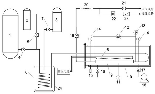
[0021] Such as figure 1As shown, the present invention includes a low-temperature self-pressurized storage tank 1, a nitrogen cylinder 2, a liquid nitrogen cylinder 3, a pressure regulating valve 4, a nitrogen valve 5, a wide-mouth Dewar 6, a liquid nitrogen valve 7, and an electric heating device 8, to be tested Heat exchange equipment 9, test vacuum dewar 10, wall temperature sensor 11, inlet and outlet differential pressure sensor 12, inlet pressure sensor 13, inlet and outlet temperature sensor 14, vacuum gauge 15, vacuum valve 16, evacuation valve 17, vacuum pump 18, Flow regulating valve 19, vaporizer 20, vent valve 21, on-off valve 22, gas flow meter 23, cooling coil 24. Among them, the cooling coil 24 is placed in the wide-mouth Dewar 6 to form a pre-cooling device; the vacuum pump 18 is connected to the test vacuum Dewar 10 thr...


PUM


Abstract

The present invention provides a testing system for researching flow boiling heat transfer character and pressure drop character of cryogenic fluid, which belong to the technical field of cryogenic engineering and cryogenic technique. The testing system comprises a cryogenic self-pressurized storage tank, a nitrogen steel cylinder, a liquid nitrogen steel cylinder, a wide-mouth dewar, a cooling coil, an electric heating device, heat exchange equipment to be tested, a test vacuum dewar, a temperature transducer, a pressure transducer, a differential pressure transducer, a vaporizer and a gas flowmeter. The cryogenic self-pressurized storage tank is used as a pressurization device in the testing system and cryogenic fluid is outputted under a certain pressure, which can simplify the testingsystem. The heat exchange equipment to be tested is arranged in the test vacuum dewar for reducing heat loss in the testing. A vacuum valve is arranged in the test vacuum dewar and can be connected to outer high pressure nitrogen for blowing the inner part of the test vacuum dewar when necessary, which can improve the system safety. The testing system has the advantages of less land occupation, small investment, simple control, easy operation, safe, reliable and applicability to various cryogenic fluids including flammable and explosive cryogenic fluids.

Description

technical field : [0001] The invention relates to a test system for studying flow boiling heat transfer characteristics and pressure drop characteristics of low temperature fluids, in particular to a test system for flow boiling heat transfer of various low temperature fluids with a saturation temperature above 77K, including flammable and explosive low temperature fluids A test system for characteristics and pressure drop characteristics belongs to the field of cryogenic engineering and cryogenic technology. Background technique: [0002] The research on the flow boiling heat transfer characteristics and pressure drop characteristics of cryogenic fluids is one of the most important basic researches in the field of low temperature. Understanding the flow boiling heat transfer characteristics and pressure drop characteristics of cryogenic fluids is helpful for guiding related cryogenic fluid heat exchangers, such as The optimal design of vaporizer and evaporator is very impor...

Claims


Application Information

Patent Timeline
IPC IPC(8): G01N25/20G01N33/00
Inventor 石玉美陈东升于忠杰
Owner SHANGHAI JIAO TONG UNIV
Learn More