Pulse ignition system of field effect ion induction stove

An ion induction and pulse ignition technology, applied in applications, household appliances, household stoves/stoves, etc., can solve the problems of large insertion loss, flammable gas leakage, and low input impedance, and achieves solutions to solve insertion loss and improve reliability. Effect

Inactive Publication Date: 2015-04-29
中山市奥森电子有限公司
View PDF5 Cites 0 Cited by
  • Summary
  • Abstract
  • Description
  • Claims
  • Application Information

AI Technical Summary

Problems solved by technology

Cause flammable gas leakage, there is a serious safety hazard
[0008] 3. When the cooker is in use, when the soup overflows and pours onto the flame detection needle, the igniter will cause the cooker to shut down incorrectly under the condition of normal combustion.
[0009] 4. The igniter is used on the stove of the infrared burner. If the soup overflows between the flame detection needle and the ceramic plate, it will cause the flame to go out without closing the solenoid valve and cause gas leakage. This is a fatal safety hazard. Such phenomena can easily cause fire or gas explosion
[0010] 5. Since the negative voltage of the ion induction pulse igniter currently used in the market is an analog negative voltage, the input impedance is small and the insertion loss is large
Affected by the electrical conductivity of the burner material and coating, the igniter used on the burner with poor conductivity often works at full power, which consumes a lot of power, does not save electricity, does not save energy, is not environmentally friendly, and has a short service life of the battery. And this is the main shortcoming of traditional technology

Method used


Image

  • Pulse ignition system of field effect ion induction stove
  • Pulse ignition system of field effect ion induction stove

Examples


Embodiment Construction

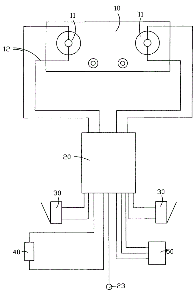
[0020] Such as Figures 1 to 2 As shown, a field effect ion induction cooktop pulse ignition system includes a cooktop 10 , an igniter 20 , a start switch 30 , a battery assembly 40 and a solenoid valve 50 .

[0021] Wherein, the cooker 10 has several burners 11 .

[0022] The igniter 20 is connected to several burners 11 of the cooker 10 through several high-voltage ignition lines 121 and flame detection lines 122 respectively,

[0023] During specific implementation, each burner head 11 is connected to the igniter 20 through a high-voltage ignition line 121 and a flame detection line 122 .

[0024] The flame detection line 122 is used to transmit the combustion status signal of the burner 11 to the igniter 20 .

[0025] The start switch 30 , the battery assembly 40 and the solenoid valve 50 are respectively connected to the igniter 20 .

[0026] Wherein, the start switch 30 is used to provide the igniter 20 with a signal for igniting or extinguishing the fire.

[0027] T...


PUM


Abstract

The invention relates to a pulse ignition system of a field effect ion induction stove. The pulse ignition system comprises a stove, an igniter, a starting switch, a battery assembly and an electromagnetic valve, wherein the stove is provided with a plurality of burners; the igniter is respectively connected with the plurality of burners of the stove through a plurality of flame detection wires; the flame detection wires are used for transmitting the burning state signals of the burners to the igniter; the starting switch, the battery assembly and the electromagnetic valve are respectively connected with the igniter; the starting switch is used for providing an ignition or fire extinguishing signal for the igniter; the battery assembly is used for supplying power to the igniter; the electromagnetic valve is arranged in a gas passage; the igniter controls the opening and closing state of the electromagnetic valve, so that the igniter controls gas supply of the stove by means of the electromagnetic valve; and the igniter comprises a singlechip and a field effect tube, and the field effect tube is connected with the singlechip.

Description

technical field [0001] The invention relates to an ignition control system for a cooker, in particular to an ignition system for a cooker that detects and controls the ignition state of the cooker through a field effect tube. Background technique [0002] As we all know, with the progress of society, more and more appliances that can improve the quality of people's daily life are becoming more and more common in people's lives. Gas cookers are such appliances. Gas cookers generally use natural gas, liquefied petroleum gas 1. Artificial gas is used as a fuel to burn a stove, and the use of a gas stove to assist people in cooking food can improve cooking efficiency and simplify people's cooking work. [0003] The ignition methods adopted in the market for gas cookers mainly include the use of tinder, manual ignition with a point gun, piezoelectric ignition, and pulse ignition. [0004] Now the country compulsorily requires all cookers to have a flameout safety protection devi...

Claims


Application Information

Patent Timeline
Patent Type & Authority Patents(China)
IPC IPC(8): F24C3/10F24C3/12
Inventor 张永红张合黄阳星
Owner 中山市奥森电子有限公司
Why Eureka
Try Eureka