Phase modulator for optical signal using multimode interference couplers

A multi-mode interference and signal technology, applied in optics, instruments, nonlinear optics, etc., can solve problems such as impracticality and large inherent insertion loss, and achieve the effects of low cost, simplified structure and high output

Pending Publication Date: 2021-02-26
UNIV COLLEGE CORK NAT UNIV OF IRELAND CORK
View PDF1 Cites 0 Cited by
  • Summary
  • Abstract
  • Description
  • Claims
  • Application Information

AI Technical Summary

Problems solved by technology

However, implementing these solutions is not practical due to the large inherent insertion loss due to the number and complexity of these components

Method used


Image

  • Phase modulator for optical signal using multimode interference couplers
  • Phase modulator for optical signal using multimode interference couplers
  • Phase modulator for optical signal using multimode interference couplers

Examples


Embodiment 1

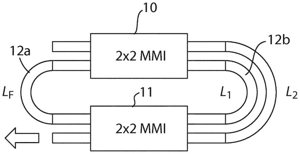
[0059] Example 1: BPSK modulated laser resonator based on two 2×2MMI devices

[0060] image 3 shows how two 2x2 MMI devices 10, 11 are coupled together and the two connecting arms are biased such that the gain in the connecting arms changes the optical output of the first MMI device 10, which is then input to the second In the MMI device 11, the generated output is BPSK. The resonance is produced by looping back one of the outputs 12 a of the second MMI device 11 into one of the inputs of the first MMI device 10 . By modulating through connection loop 12b (shown as L 1 and L 2 ) light to generate BPSK signal.

Embodiment 2

[0061] Example 2: BPSK modulated laser resonator based on 3×3MMI device

[0062] Figure 4 A 3x3 MMI device configuration based on a mirror-symmetrical 1x2 MMI device denoted by reference numeral 20 is shown. The MMI device 20 may have its off-center ports 22 and 23 looped together to form a resonance. The central port 21 can be used as an output. By changing the bias on the loop arms 22, 23, the phase of the output of the MMI device 21 can be shifted to generate a BPSK signal.

Embodiment 3

[0063] Embodiment 3: BPSK mirror based on 4×4MMI device circuit

[0064] Figure 5 A single 4x4 MMI device 30 is shown, which may be configured as a highly reflective mirror with a laser resonator drive input 31 . If the inner loop 32(L 内 ) and the outer loop 33 (L 外 ) at the same power, the highly reflective mirror will reflect all the light back (neglecting the losses of waveguides and MMI devices, etc.). If the power in the inner and outer loops is modulated, a BPSK signal will be produced on the output waveguide 34 .


PUM


Abstract

The invention provides an optical system and method for outputting a modulated signal comprising a single multimode interference (MMI) device having at least two inputs configured with a fixed phase and an output, wherein the output modulated signal is controlled by modulating the input power of at 5 least one of the inputs. The invention only requires a single MMI device to operate as the relative phase between the two inputs are fixed relative each other and one of the inputs can be used to modulate the output by modulating the power at a single input. In further embodiments, the invention shows how correct phases can be set by a single MMI device. Thus, no more than two 10 MMIs are required in conjunction with phase or amplitude modulating elements to fully generate a BPSK or QPSK signal.

Description

technical field [0001] The present disclosure relates to a phase modulator as well as an amplitude modulator. Background technique [0002] Increasing communication demands mean that faster and more efficient technologies are required to ensure further increases in bandwidth. Electrically wired and wireless communications reached their limits decades ago when simple on-off keying (OOK) was used. Instead, phase modulation techniques and the addition of parallel channels. Optical communications have historically employed OOK, but recently there has been an active shift to advanced modulation techniques, especially in long-distance fiber optic communications. [0003] Currently, these advanced modulation techniques require the use of phase modulators, especially the ubiquitous Mach-Zehnder modulator (MZM). Mach-Zehnder modulators are relatively large, generally not very energy-efficient, and have very different material requirements for lasers, making the integration of lase...

Claims


Application Information

Patent Timeline
IPC IPC(8): H04B10/556G02F1/225
CPCH04B10/5561G02F1/225H04B10/5053H04B10/548G02F1/217G02F1/21H04B10/505
Inventor F·彼得斯S·达根
Owner UNIV COLLEGE CORK NAT UNIV OF IRELAND CORK
Why Eureka
Try Eureka