
Method for leaching manganese from manganese-rich slag

A manganese-rich slag and leaching technology is applied in the field of manganese leaching from manganese-rich slag, which can solve the problems of difficult leaching of manganese-rich slag, affecting filtration, and difficulty in leaching of manganese-rich slag, and achieves improved leaching efficiency, strong feasibility and effect. significant effect

Active Publication Date: 2012-03-07
YUNNAN JIANSHUI MANGANESE
View PDF0 Cites 4 Cited by
  • Summary
  • Abstract
  • Description
  • Claims
  • Application Information

AI Technical Summary

Problems solved by technology

The manganese content in the manganese-rich slag is generally 25-40wt%, but the leaching of the manganese-rich slag has always been difficult, and because of its particularly high silicon content (generally around 30wt%), the filtration is seriously affected after leaching, and the leaching of the manganese-rich slag has always been is a worldwide problem

Method used


Image

  • Method for leaching manganese from manganese-rich slag
  • Method for leaching manganese from manganese-rich slag

Examples


example 1

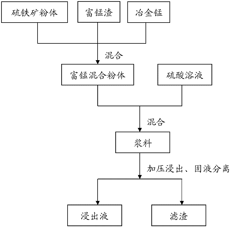
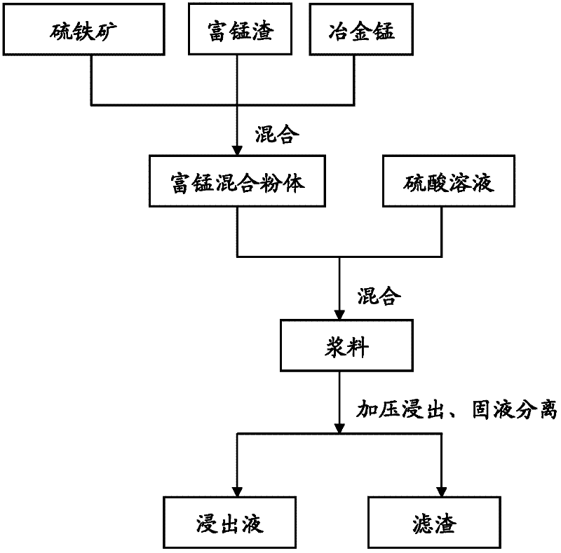
[0041] First, mix 40 grams of manganese-rich slag (manganese content 29.11wt%, silica 27.38wt%) with 60 grams of metallurgical manganese (manganese content 21.14wt%, silica 6.69wt%), and add 30 grams of yellow iron Ore (containing FeS 2 about 70 wt%).

[0042] Next, a sulfuric acid solution with an acidity of 100 g / L was added to the above mixed powder with a liquid-solid ratio of 6:1 to obtain a slurry.

[0043] Finally, under the conditions of temperature 110° C. and pressure 0.5 MPa, leaching was carried out for 2 hours while vigorously stirring. The leached feed liquid is vacuum filtered while hot to obtain manganese leaching liquid and filter residue.

[0044] The filtrate was measured and volumetrically sent for sample analysis, and the filter residue was dried and weighed for sample analysis.

[0045] And the leaching rate measured by leachate and the leached rate measured by filter residue are calculated respectively by the following calculation formula:

[0046] L...

example 2

[0055] First, as in Example 1, 40 grams of manganese-rich slag (manganese content 29.11wt%, silicon dioxide 27.38wt%) and 60 grams of metallurgical manganese (manganese content 21.14wt%, silicon dioxide 6.69wt%) were evenly mixed , and add an appropriate amount of pyrite.

[0056] Next, add sulfuric acid with an acidity of 130 g / L to the above mixed powder with a liquid-solid ratio of 7:1 to obtain a slurry.

[0057]Finally, under the conditions of temperature 100° C. and pressure 0.3 MPa, leaching was carried out for 2 hours while vigorously stirring. The leached feed liquid is filtered under pressure while hot to obtain manganese leaching liquid and filter residue.

[0058] The filtrate was measured and volumetrically sent for sample analysis, and the filter residue was dried and weighed for sample analysis.

[0059] Similarly, the leaching rate was calculated by the above calculation method, and the results showed that the leaching rate was 93.6% in terms of leachate and ...


PUM


Abstract

The invention discloses a method for leaching manganese from manganese-rich slag. The method comprises steps that: (a) the manganese-rich slag is mixed with metallurgy manganese and pyrite powder, such that manganese-rich mixed powder is obtained; (b) a sulfuric acid solution and the manganese-rich mixed powder are mixed, such that a slurry is obtained; (c) the slurry is stirred, and is simultaneously processed through pressure leaching; the leached slurry is filtered, such that a leachate and filter residue are obtained. According to the method provided by the embodiment of the invention forleaching manganese from manganese-rich slag, simultaneous leaching of low-silicon low-grade metallurgy manganese can be realized while filtering is carried out. Also, because a pressure leaching technology is adopted, the leaching efficiency is greatly improved. According to the method provided by the embodiment of the invention for leaching manganese from manganese-rich slag, higher than 90% of manganese can be leached from the manganese-rich slag. Also, the method provided by the invention is advantaged in simple technology, high feasibility, and substantial effect.

Description

technical field [0001] The invention belongs to the field of hydrometallurgy, in particular to a method for leaching manganese from manganese-rich slag. Background technique [0002] In the field of hydrometallurgy, large amounts of manganese-rich slag are produced as a by-product. The manganese content in the manganese-rich slag is generally 25-40wt%, but the leaching of the manganese-rich slag has always been difficult, and because of its particularly high silicon content (generally around 30wt%), the filtration is seriously affected after leaching, and the leaching of the manganese-rich slag has always been It is a worldwide problem. Contents of the invention [0003] The present invention aims to solve at least one of the above-mentioned technical problems. [0004] For this reason, an object of the present invention is to propose a method for leaching manganese from manganese-rich slag that can effectively leach manganese-rich slag, has a simple process, is easy to ...

Claims


Application Information

Patent Timeline
IPC IPC(8): C22B7/00C22B3/08C22B3/22C22B47/00
CPCY02P10/20
Inventor 王吉坤彭东张承贵嵇晓沧马进闫江峰任敏张红耀杨世诚李辉张学文谢红艳
Owner YUNNAN JIANSHUI MANGANESE
Learn More