
Dynamic range compressor-limiter and low-level expander with look-ahead for maximizing and stabilizing voice level in telecommunication applications

Inactive Publication Date: 2003-03-18
K S WAVES
View PDF7 Cites 116 Cited by
  • Summary
  • Abstract
  • Description
  • Claims
  • Application Information

AI Technical Summary

Benefits of technology

It is an object of the present invention to provide a method for processing speech signals that provides an optimal solution for all the previously-mentioned problems, and allows for maximizing and stabilizing the RMS voice level, significantly reducing the peak-to-RMS ratio, and avoiding excessive amplification of background noise.

Problems solved by technology

On the other hand, the reproduction circuitry of common telephones are limited in their dynamic range, especially for cellular phones where supply voltage, physical size, and cost are a further limiting factor.
There are three major problems associated with dynamic range in telephony applications: the high peak-to-RMS ratio naturally characteristic of speech signals; the wide variations in RMS level of speech signals; and the high level of background noise typically encountered in telephony applications.
None of the prior art methods, however, fully address all of the above-mentioned problems, but provide for only limited improvements.
While such limited improvements may have been sufficient for traditional telephony, they are not adequate to deal with the more severe problems posed by cellular / mobile telephony.
On the other hand, controlling signal peaks demands a short response time, and therefore controlling signal peaks is not possible when a slow response time is used.
Another limitation of prior art methods is that they deal with both the AGC of the speech signal, as well as with the muting or reduction of background noise traveling through the same signal path.
Because of this, the performance of such methods is degraded.

Method used


Image

  • Dynamic range compressor-limiter and low-level expander with look-ahead for maximizing and stabilizing voice level in telecommunication applications
  • Dynamic range compressor-limiter and low-level expander with look-ahead for maximizing and stabilizing voice level in telecommunication applications
  • Dynamic range compressor-limiter and low-level expander with look-ahead for maximizing and stabilizing voice level in telecommunication applications

Examples


Embodiment Construction

As previously noted, the three major problems associated with dynamic range in telephony applications are the high peak-to-RMS ratio natural to speech signals, the wide variations in RMS level of speech signals, and the high level of background noise typical to telephony applications.

The principles and operation of a compressor-limiter / low-level expander according to the present invention may be understood with reference to the drawings and the accompanying description.

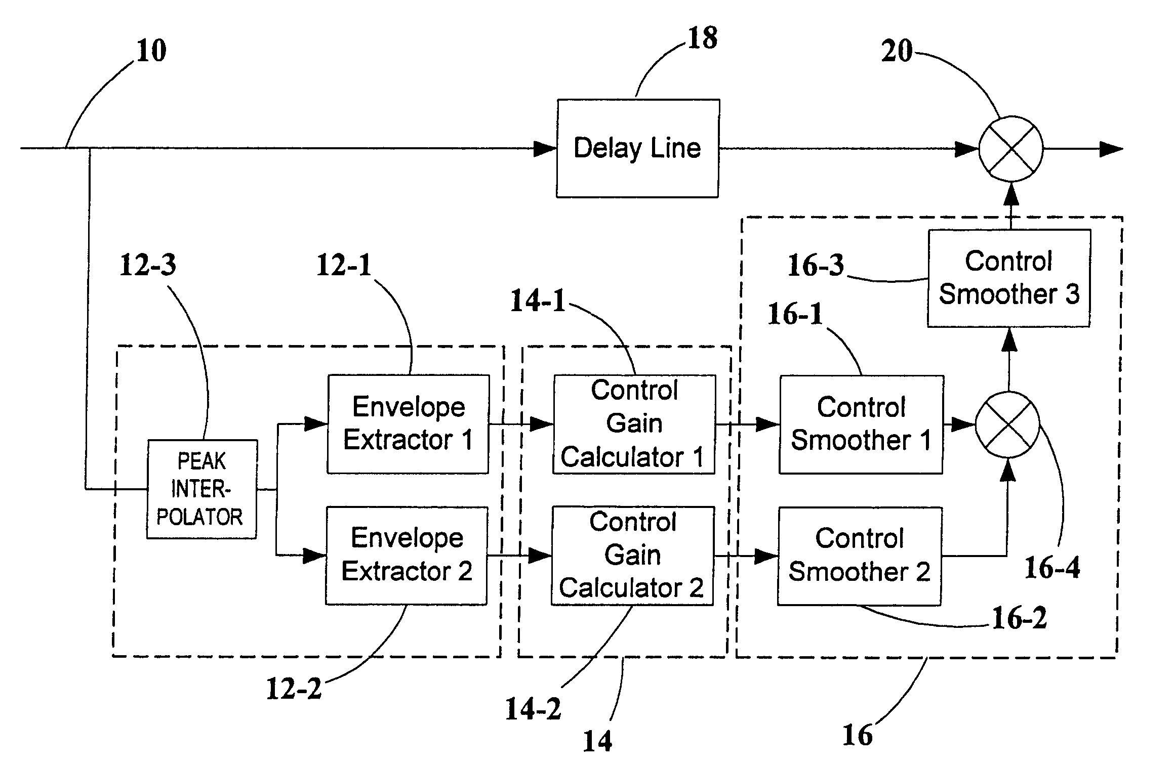
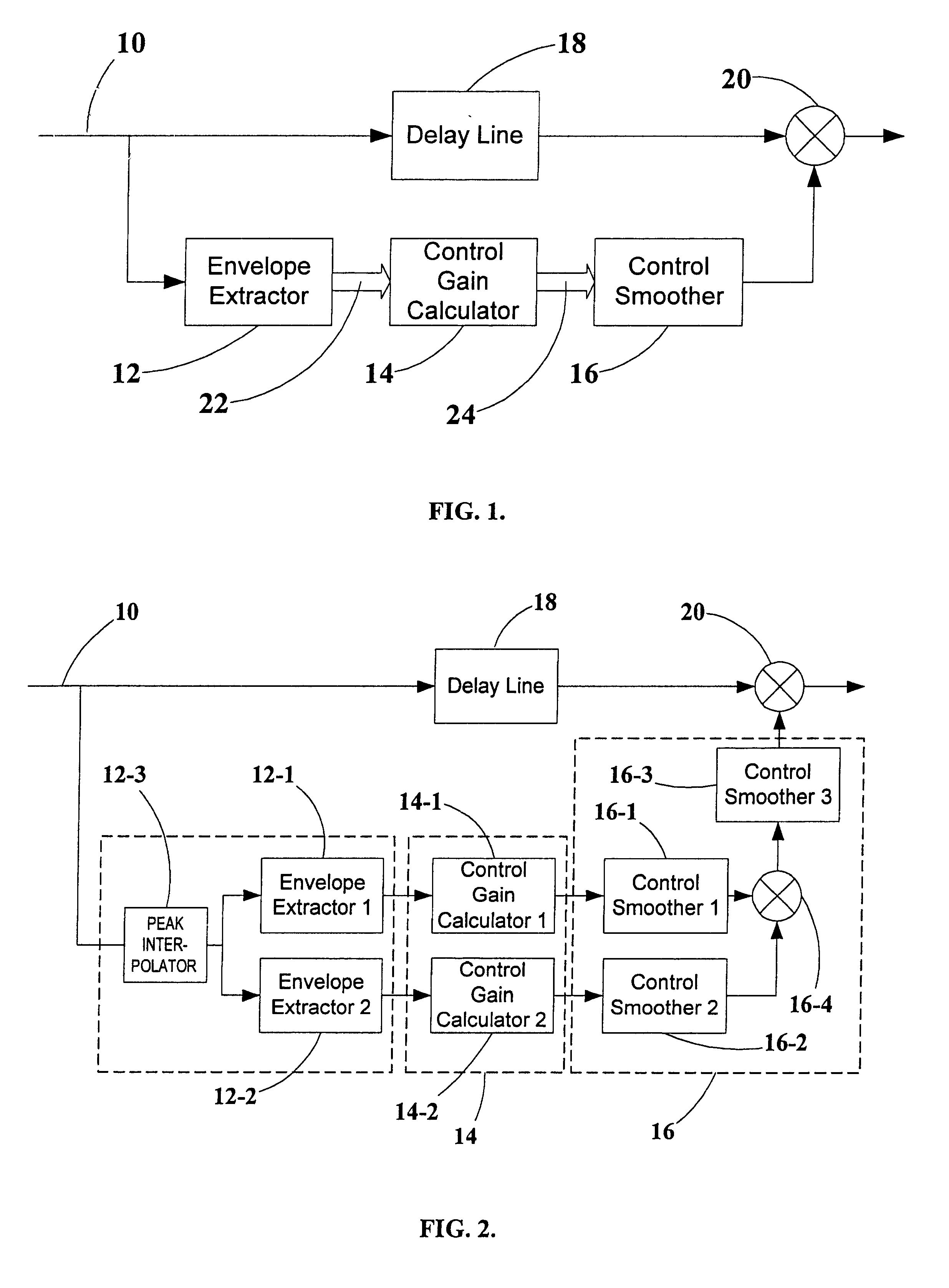
FIG. 2 shows an embodiment of the invention where two parallel control paths are used. The general blocks including envelope extractor 12, control gain calculator 14, control smoother 16, and delay line 18 retain the same functionality as previously illustrated in FIG. 1. The detailed internal structure of each block supports two parallel paths. The first path consists of a first envelope extractor 12-1, a first control gain calculator 14-1, and a first control smoother 16-1 and is designed to deliver limiting and dyn...


PUM


Abstract

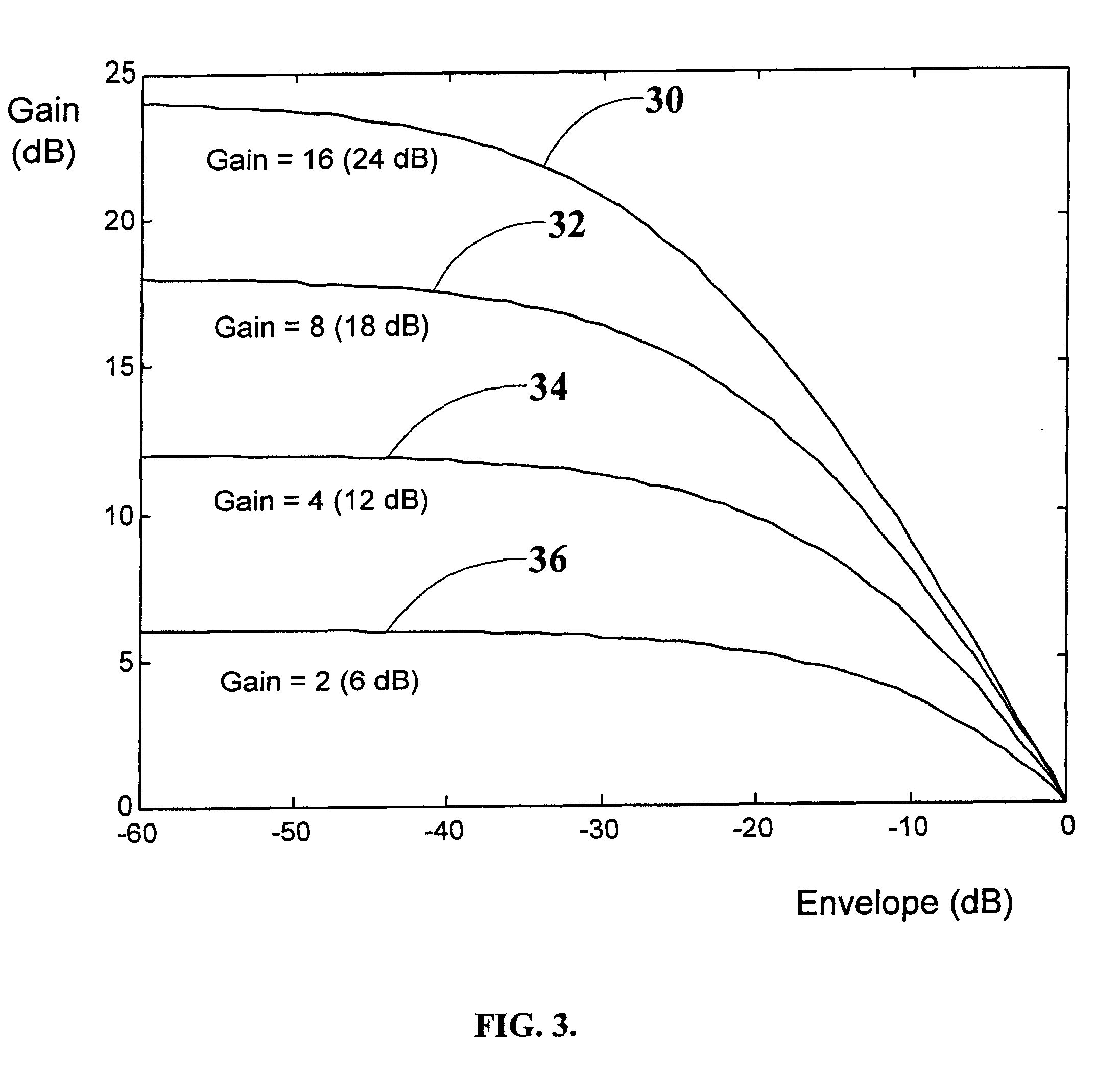
A voice signal processing system with multiple parallel control paths, each of which address different problems, such as the high peak-to-RMS signal ratios characteristic of speech, wide variations in RMS speech levels, and high background noise levels. Different families of input-output control curves are used simultaneously to achieve efficient peak limiting and dynamic range compression as well as low-level dynamic expansion to prevent excessive amplification of background noise. In addition, a delay in the audio path relative to the control path makes it possible to employ an effective look-ahead in the control path, with FIR filtering smoothing-matched to the look-ahead. Digital domain peak interpolators are used for estimating the peaks of the input signal in the continuous time domain.

Description

FIELD OF THE INVENTIONThe present invention relates to voice processing and, more particularly, to voice processing for telecommunication and other narrow dynamic range voice communication systems, where it is desired to maximize and stabilize the level of received or transmitted speech.BACKGROUND OF THE INVENTIONSpeech signals are characterized by a large dynamic range and a high peak-to-RMS ratio. In telephony applications, especially cellular telephony, this dynamic range is further exaggerated due to variations in relative positioning of the talker and microphone, variations of voice level between different talkers, variations in same talker's voice level, and similar variable factors.On the other hand, the reproduction circuitry of common telephones are limited in their dynamic range, especially for cellular phones where supply voltage, physical size, and cost are a further limiting factor. An extreme example is the cellular / mobile speakerphone, where despite severe restriction...

Claims


Application Information

Patent Timeline
IPC IPC(8): H03G7/00
CPCH03G7/002
Inventor SHASHOUA, MEIR
Owner K S WAVES
Learn More