
Method for realizing automatic debugging of wireless microphone and automatic debugging system

A wireless microphone and automatic debugging technology, applied in electrical components, electrostatic transducer microphones, etc., can solve problems such as unfavorable efficiency and large workload.

Inactive Publication Date: 2012-02-15
周意春
View PDF8 Cites 7 Cited by
  • Summary
  • Abstract
  • Description
  • Claims
  • Application Information

AI Technical Summary

Problems solved by technology

[0021] In the existing technology, the above debugging points all need to be manually debugged, the workload is heavy during mass production, and the same work is repeated, which is not conducive to improving efficiency

Method used


Image

  • Method for realizing automatic debugging of wireless microphone and automatic debugging system
  • Method for realizing automatic debugging of wireless microphone and automatic debugging system
  • Method for realizing automatic debugging of wireless microphone and automatic debugging system

Examples


Embodiment Construction

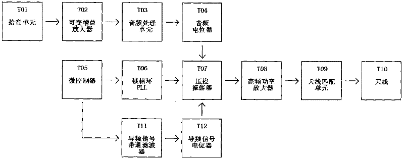
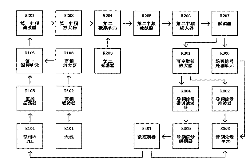
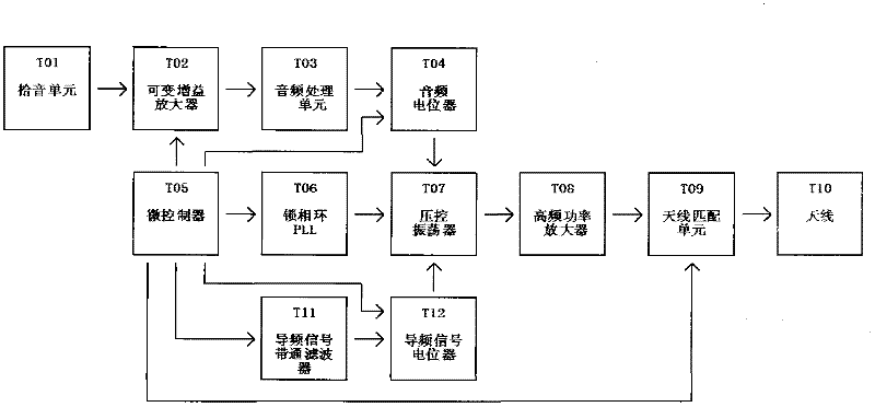
[0036] For adjusting the potentiometer, change the potentiometer to a digital potentiometer (except for the field strength signal processing unit). The potentiometer part of the digital potentiometer is connected to the original potentiometer position, and the control part of the digital potentiometer is connected to the microcontroller. The digital potentiometer is controlled by the microcontroller, and the tap position of the potentiometer is changed to change the output signal amplitude of the potentiometer, or to change the input resistance and feedback resistance of the amplifier to achieve amplifier gain adjustment.

[0037] For adjusting the trimmer capacitor, the trimmer capacitor is changed to a varactor diode, and the pulse level with variable duty ratio output by the microcontroller is controlled by a smooth voltage signal through a passive low-pass filter. Changing the pulse duty cycle also changes the varactor junction capacitance. It can also be a digital potent...


PUM


Abstract

The invention relates to an automatic debugging system for testing a wireless microphone, which comprises a transmitter test fixture, a receiver test fixture, a testing computer, testing computer software and instrument equipment which can be connected to the computer for realizing control on the basis of the computer software. The invention also relates to a method for automatically debugging the wireless microphone through the debugging system. By the debugging system and the debugging method, the complete automatic debugging in the process of producing the wireless microphone is realized.

Description

technical field [0001] The invention relates to a wireless microphone, and further relates to a method for realizing automatic debugging during production of the wireless microphone and an automatic debugging system thereof. Background technique [0002] A wireless microphone, or a wireless microphone, is an audio equipment that transmits sound signals. It consists of a transmitter and a receiver. It is usually called a wireless microphone system. It is essentially a one-way wireless communication system. The early wireless microphones were realized by FM frequency modulation, and later a quartz oscillator was used to generate accurate and stable fixed frequencies for transmission and reception. This kind of microphone and receiver only fixed a single frequency paired for use. Now professional wireless microphones are all using frequency synthesis (PLL Synthesized), which can switch the desired working channel arbitrarily within the preset bandwidth, so as to avoid environm...

Claims


Application Information

Patent Timeline
Patent Type & Authority Applications(China)
IPC IPC(8): H04R19/04H04R29/00
Inventor 周意春
Owner 周意春
Learn More