
Ultrathin glass corner machining method and special computerized numerical control (CNC) cutter

A technology of ultra-thin glass and processing method, which is applied in the direction of manufacturing tools, metal processing equipment, machine tools suitable for grinding the edge of workpieces, etc. The effect of improving efficiency, improving the pass rate, and not easy to scratch

Inactive Publication Date: 2012-02-15
ZHEJIANG XINGXING TECH CO LTD
View PDF4 Cites 23 Cited by
  • Summary
  • Abstract
  • Description
  • Claims
  • Application Information

AI Technical Summary

Problems solved by technology

The finishing process for ultra-thin glass from 0.4mm to 2.5mm is generally: cutting, profiling, CNC (CNC machine tool) shape and drilling, cleaning, CNC chamfering, polishing, sweeping, ultrasonic cleaning However, due to the brittleness of the glass itself, the ultra-thin glass processing technology in the industry can only realize the finishing of a single piece of ultra-thin glass; a single piece of ultra-thin glass needs to be chamfered on a single side, and then Then turn it over to perform chamfering on the other side, and the processing efficiency is relatively low; for the corner processing of each piece of ultra-thin glass, the corner processing needs to be manually replaced, which requires a lot of labor and equipment to match, and the investment cost is relatively high. ;Because the single-chip processing process is very likely to produce substandard products, resulting in a lower product qualification rate

Method used


Image

  • Ultrathin glass corner machining method and special computerized numerical control (CNC) cutter
  • Ultrathin glass corner machining method and special computerized numerical control (CNC) cutter
  • Ultrathin glass corner machining method and special computerized numerical control (CNC) cutter

Examples


Embodiment 1

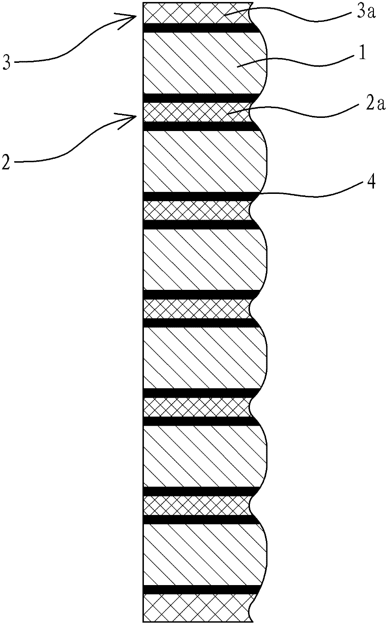
[0031] For the simultaneous chamfering of the upper and lower sides of each glass 5, a special CNC tool 6 is configured, and the two chamfering slopes of the convex ring chamfering portion 5a form an acute angle; the special CNC tool 6 is as follows: Figure 5 shown.

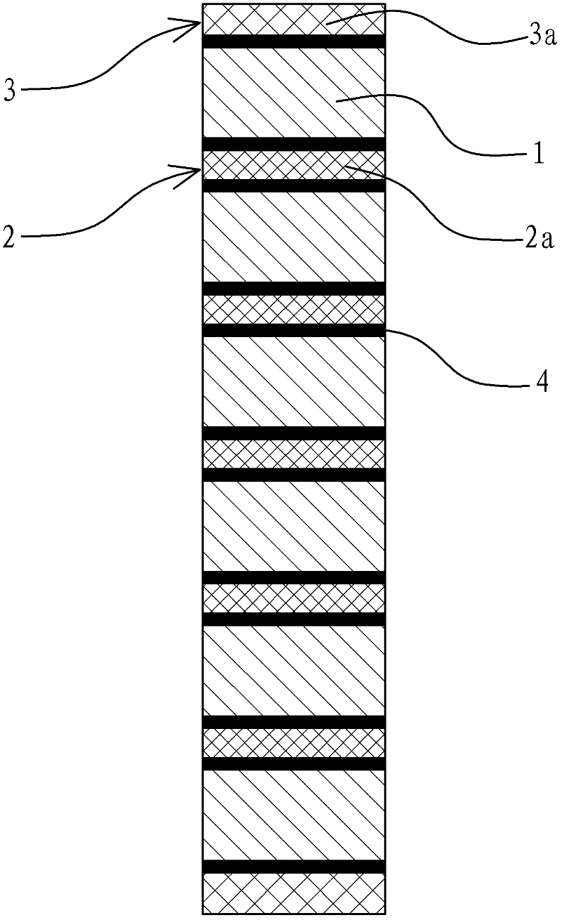
[0032] Such as figure 1As shown, the original glass sheet with a thickness of 0.85mm is selected, and the glass sheet can be flat glass or curved glass. Use a cutting machine to cut into several single-piece rectangular sheets according to the size and shape of the product design. The several single-piece rectangular sheets can be directly purchased or customized in the market. Take six pieces of single-piece glass 1 and stack them into a rectangular block For glass, a spacer layer 2 with a thickness of 1mm is arranged between every adjacent two pieces of single glass 1. The specific structure of the spacer layer 2 is: take a spacer 2a with a thickness of 0.6mm, and place it on top of the spacer 2a. Both the s...

Embodiment 2

[0034] For simultaneous chamfering of the upper and lower sides of multiple pieces of glass, a special CNC tool 27 is configured, and the two chamfering slopes of the convex ring chamfering part 5a form an obtuse angle; Figure 6 shown.

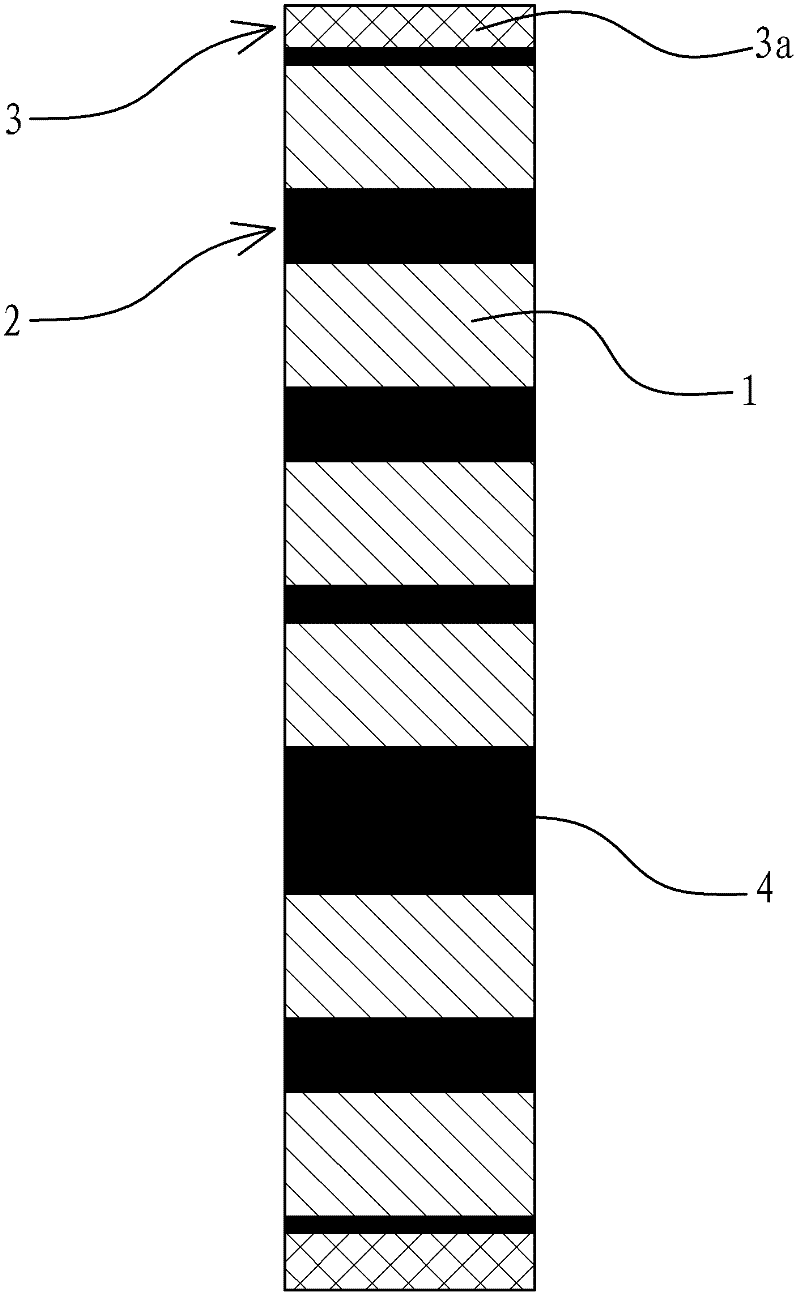
[0035] Such as image 3 As shown, the structure of this embodiment is basically the same as that of Embodiment 1, the difference is that: take six pieces of monolithic glass 1 to be superimposed on each other to form a rectangular block glass, and arrange A spacer layer 2 with a thickness of 1mm, 1mm, 0.5mm, 2mm, and 1mm, the spacer layer 2 is directly formed by an adhesive 4, and each adjacent two pieces of single glass 1 are connected by an adhesive 4, such as Figure 4 As shown, according to the thickness of the monolithic glass 1 and the thickness of the adhesive 4 bonded between the monolithic glass 1, a pair of each monolithic glass 1 is processed at the same time. The two chamfering slopes of the first convex annular chamfering porti...

Embodiment 3

[0037] For the simultaneous chamfering of the upper sides of multiple pieces of glass, a special CNC tool 3 8 is configured, and the convex ring chamfering portion 5a has only one chamfering slope; the special CNC tool 3 8 is as Figure 7 shown.

[0038] The structure of this embodiment is basically the same as that of Embodiment 2, the difference is that a pair of each single glass is set according to the thickness of the single glass 1 and the thickness of the adhesive 4 bonded between the single glass 1 1 Simultaneously process the special CNC tool 3 8 for corner processing, the convex annular chamfering portion 5a of the special CNC tool 3 8 is composed of a single chamfering slope, and the chamfering slope faces the upper side of the laminated upper and lower single glass 1 The corners are chamfered at the same time, and the lower side corners of the upper and lower single glass are not chamfered. After the special CNC tool 38 is designed, each single glass 1 in the recta...


PUM

PropertyMeasurementUnit
Thicknessaaaaaaaaaa
Thicknessaaaaaaaaaa
Thicknessaaaaaaaaaa

Abstract

The invention provides an ultrathin glass corner machining method and a special computerized numerical control (CNC) cutter, and belongs to the technical field of glass machining. The method solves the problems that the conventional single ultrathin glass can only be subjected to single-piece and single-side chamfer machining and the machining efficiency is relatively low. The ultrathin glass corner machining method mainly comprises the following steps of: taking glass sheets, superposing the glass sheets, arranging a protective layer, curing a spacing layer, arranging the special CNC cutter for simultaneously machining corners of each glass sheet in superposed rectangular blocky glasses, and performing corner grinding on each glass sheet in the superposed rectangular block glasses by a CNC machining technology. By the method, polishing is not needed after machining, the glass machining efficiency is improved exponentially, shape and chamfer machining is performed on the superposed glass sheets, the surface of the single glass sheet is not easily scratched in the machining process, the product has good consistency, the qualification rate of the product is improved, and the machining efficiency is obviously improved.

Description

technical field [0001] The invention belongs to the technical field of glass processing, and relates to an ultra-thin glass corner processing method and a special CNC cutter. Background technique [0002] Ultra-thin glass with a thickness of 0.4mm to 2.5mm is a good material commonly used in the electronic product window protection screen manufacturing industry due to its unique visual effect, protective performance and optical performance. The finishing process for ultra-thin glass from 0.4mm to 2.5mm is generally: cutting, profiling, CNC (CNC machine tool) shape and drilling, cleaning, CNC chamfering, polishing, sweeping, ultrasonic cleaning However, due to the brittleness of the glass itself, the ultra-thin glass processing technology in the industry can only realize the finishing of a single piece of ultra-thin glass; a single piece of ultra-thin glass needs to be chamfered on a single side, and then Then turn it over to perform chamfering on the other side, and the pro...

Claims


Application Information

Patent Timeline
IPC IPC(8): B24B9/08B24D3/00
Inventor 王先玉夏永光
Owner ZHEJIANG XINGXING TECH CO LTD
Learn More