Vertical air extraction preparation process of vacuum glass

A technology of vacuum glass and preparation process, which is applied in glass manufacturing equipment, glass forming, glass reshaping, etc. It can solve the problems of affecting the quality of vacuum glass, insufficient vacuum degree, and difficulty in taking over pipes, so as to realize continuous production and improve Vacuum degree, simple and easy operation

Active Publication Date: 2012-01-18
沃卡姆(山东)真空玻璃科技有限公司
View PDF5 Cites 5 Cited by
  • Summary
  • Abstract
  • Description
  • Claims
  • Application Information

AI Technical Summary

Problems solved by technology

The shortcoming that above-mentioned two kinds of methods exist is: 1, in the existing vacuum heating furnace, glass supports are placed parallelly up and down, the spacing between each layer of glass supports is 15-25cm, and each layer of glass supports is equipped with a cooling water device The suction head is connected to the suction pipe installed in the vacuum glass. The vacuum unit is installed outside the furnace, and the vacuum is sealed in the furnace, thus completing the manufacture of vacuum glass. However, this structure makes the unit volume in the furnace set Complicated, few layers, low output; 2. The existing vacuum glass suction head device has a complex structure, difficult connection, easy to break, and water cooling is prone to water leakage and cause accidents; 3. The existing vacuum glass suction pipe It is a through hole. During the cooling process of the vacuum glass after edge sealing, there is still some moisture in the vacuum chamber. Although the moisture can be absorbed by the getter, there is also the problem of insufficient vacuum degree that affects the vacuum. The quality of glass; 4. The existing heating furnace and vacuum furnace have their own functions, basically there is no organic connection, and the energy consumption is relatively large

Method used


Image

  • Vertical air extraction preparation process of vacuum glass
  • Vertical air extraction preparation process of vacuum glass
  • Vertical air extraction preparation process of vacuum glass

Examples


Embodiment Construction

[0023] The present invention will be further described in detail below in conjunction with the accompanying drawings and through specific embodiments. The following embodiments are only descriptive, not restrictive, and cannot limit the protection scope of the present invention.

[0024] In order to clearly describe the embodiment of the present invention, the manufacturing system of the present invention will be described first.

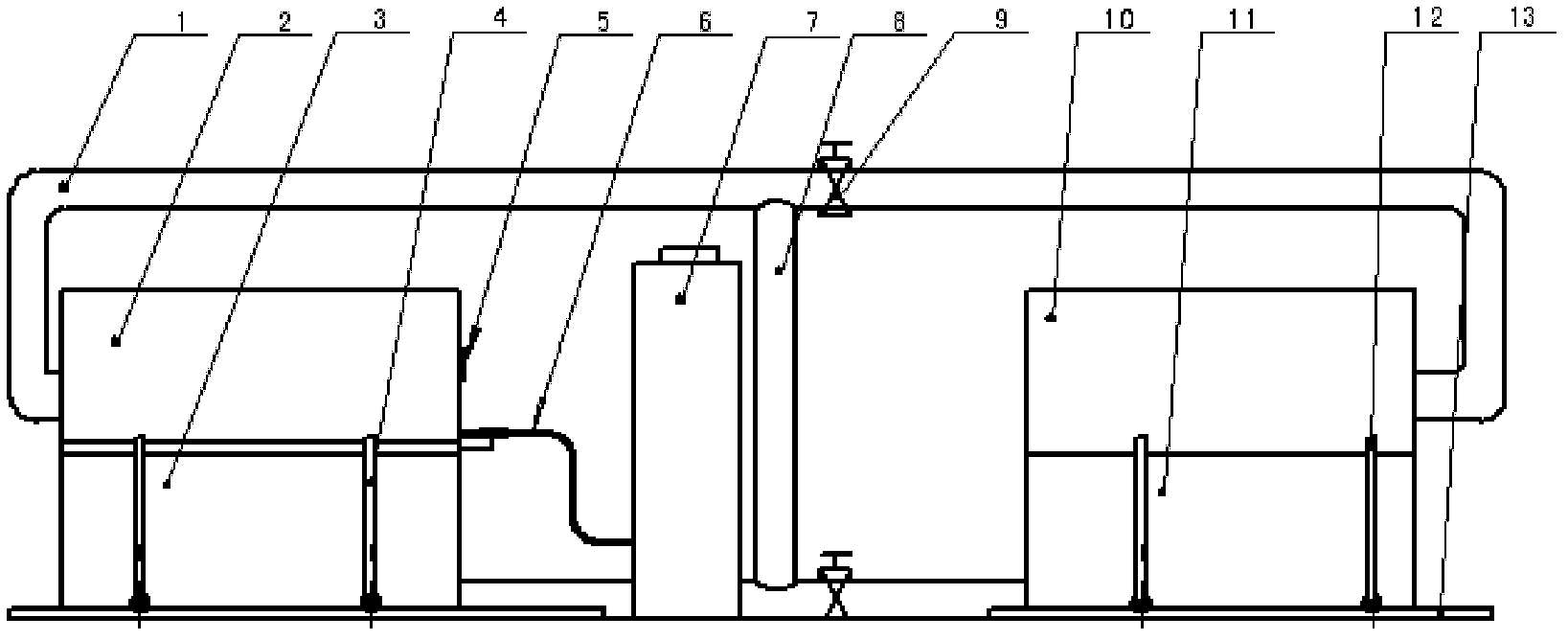
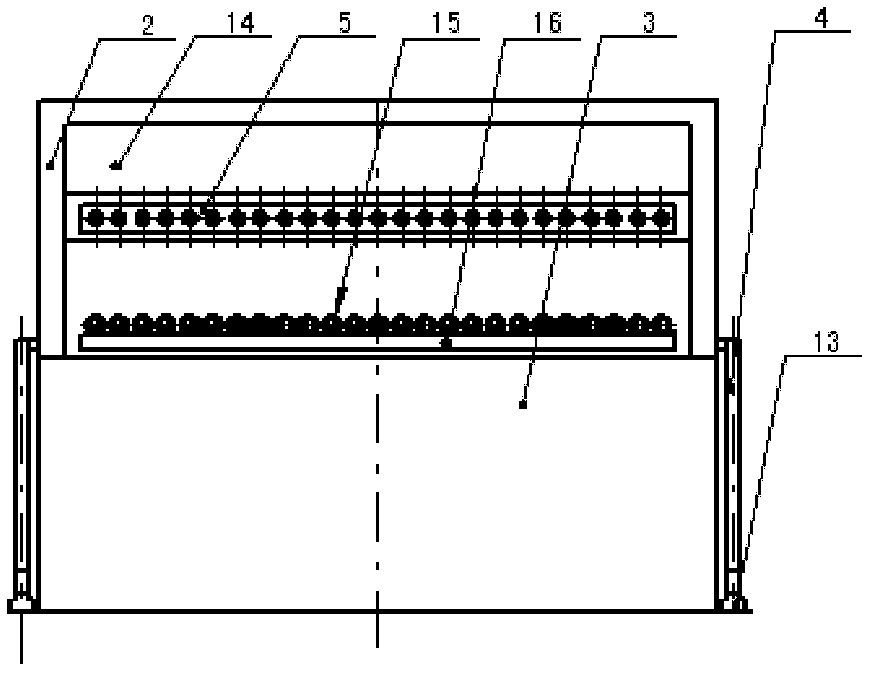
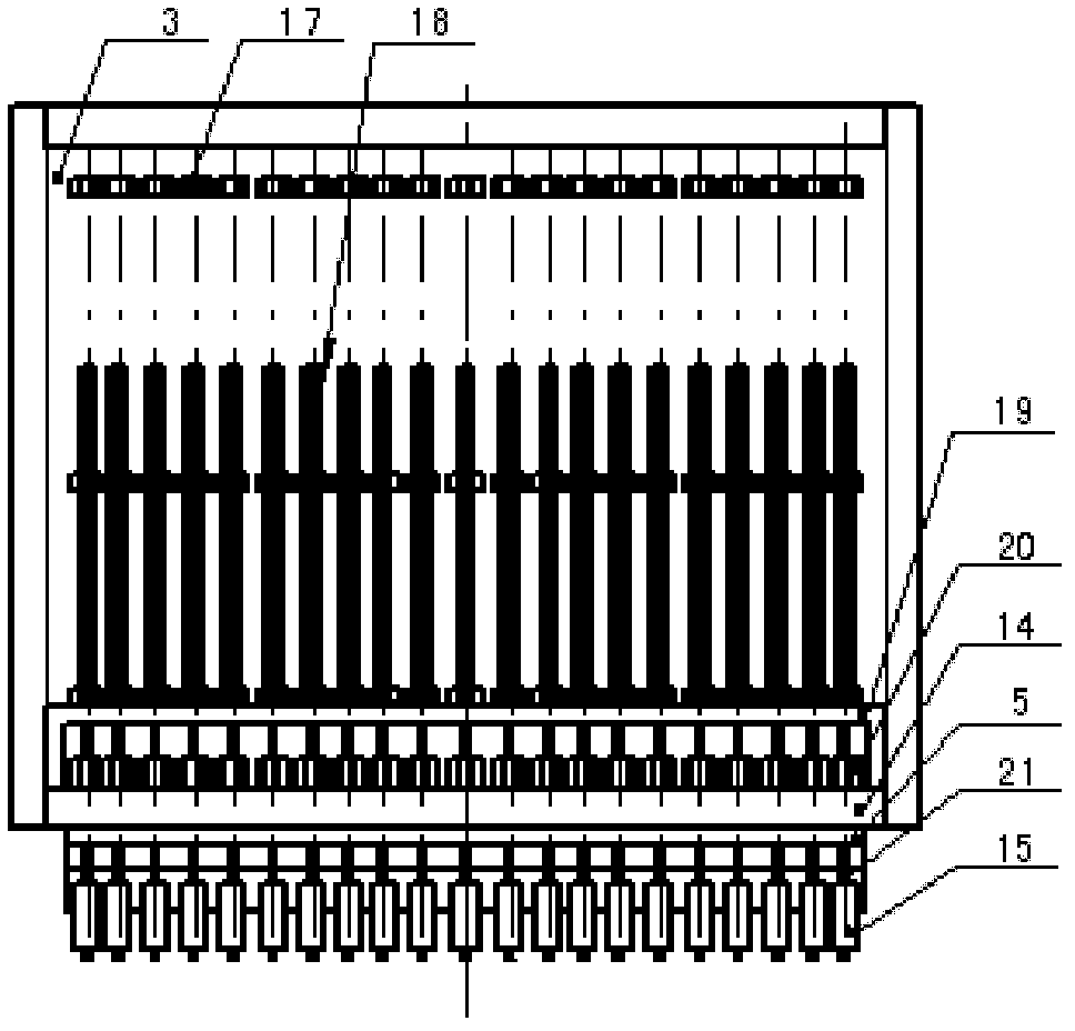
[0025] see figure 1 , 2 3. The manufacturing system includes a high-temperature heating box and a low-temperature pumping box. The high-temperature heating box is composed of a movable sealing box cover 10 and a heating box 11. The moving sealing box cover is a door-type structure, and the sealing cover is installed on the heating box. Both the box cover and the heating box are equipped with thermal insulation materials, and a mobile bracket 12 is installed on both sides of the mobile sealing box cover. The lower end of the mobile bracket is equipp...


PUM


Abstract

The invention relates to a vertical air extraction preparation process of vacuum glass. The process comprises the following steps of: (1) combining pieces: putting a support and glass powder with low melting point or adhesive between upper and lower flat glass cut pieces, and arranging an air extraction glass tube on the side or the lateral surface of a corner; (2) sealing the edges by heating ina high-temperature heating box; (3) vertically placing the edge sealed glass into a cassette fixedly arranged on a bottom plate in an air extraction box in sequence; and (4) vacuumizing: opening a vacuum pump to vacuumize the cavity in the vacuum glass, performing hot melting sealing on the air extraction tube by adopting an electric fusing electrode after the set vacuum degree is achieved, cooling the glass to room temperature and then discharging the glass out of a furnace, and thus obtaining the vacuum glass. Multiple groups of positioning assemblies are uniformly distributed and fixedly arranged in the vacuumizing furnace at intervals in the vacuum glass manufacturing system, the vacuum glass can be installed in a vertical mode or a superposition mode, and the distance between the vacuum glass pieces is shortened and can reach 0.5 to 10 centimeters by calculation, so that the production number of the vacuum glass is greatly improved, the production efficiency is improved by at least two times, and the problem of low vacuum glass yield is effectively solved.

Description

technical field [0001] The invention belongs to the field of vacuum glass, in particular to a preparation process for vacuum glass vertical suction. Background technique [0002] At present, the traditional vacuum glass manufacturing method is to lay supports on the substrate glass, and then combine the sheets, seal the edges, make air extraction holes, install air extraction pipes, and place the two pieces of glass flat in the heating furnace for heating and edge sealing. Then take it out for vacuuming, and after fusing the exhaust pipe, vacuum glass can be formed. Alternatively, heating and edge sealing and vacuuming can also be carried out directly in a vacuum heating furnace. The shortcoming that above-mentioned two kinds of methods exist is: 1, in the existing vacuum heating furnace, glass supports are placed parallelly up and down, the spacing between each layer of glass supports is 15-25cm, and each layer of glass supports is equipped with a cooling water device The...

Claims


Application Information

Patent Timeline
Patent Type & Authority Applications(China)
IPC IPC(8): C03B23/24
CPCY02P40/57
Inventor 左树森
Owner 沃卡姆(山东)真空玻璃科技有限公司
Why Eureka
Try Eureka