
Object detection method and object detection system

An object and signal technology, applied in the field of object detection method and object detection system based on tree analysis to distinguish the position of objects, can solve the problems of inconvenience for users, low anti-noise ability, etc., so as to reduce the inconvenience, Improve the speed of judgment and improve the effect of correctness

Inactive Publication Date: 2014-08-20
QISDA SUZHOU +1
View PDF2 Cites 0 Cited by
  • Summary
  • Abstract
  • Description
  • Claims
  • Application Information

AI Technical Summary

Problems solved by technology

At present, the multi-touch technology based on optical image as the basis of touch position judgment has strict requirements on the operating environment, and its anti-noise ability is low, so it causes a certain degree of inconvenience to users.

Method used


Image

  • Object detection method and object detection system
  • Object detection method and object detection system
  • Object detection method and object detection system

Examples


Embodiment Construction

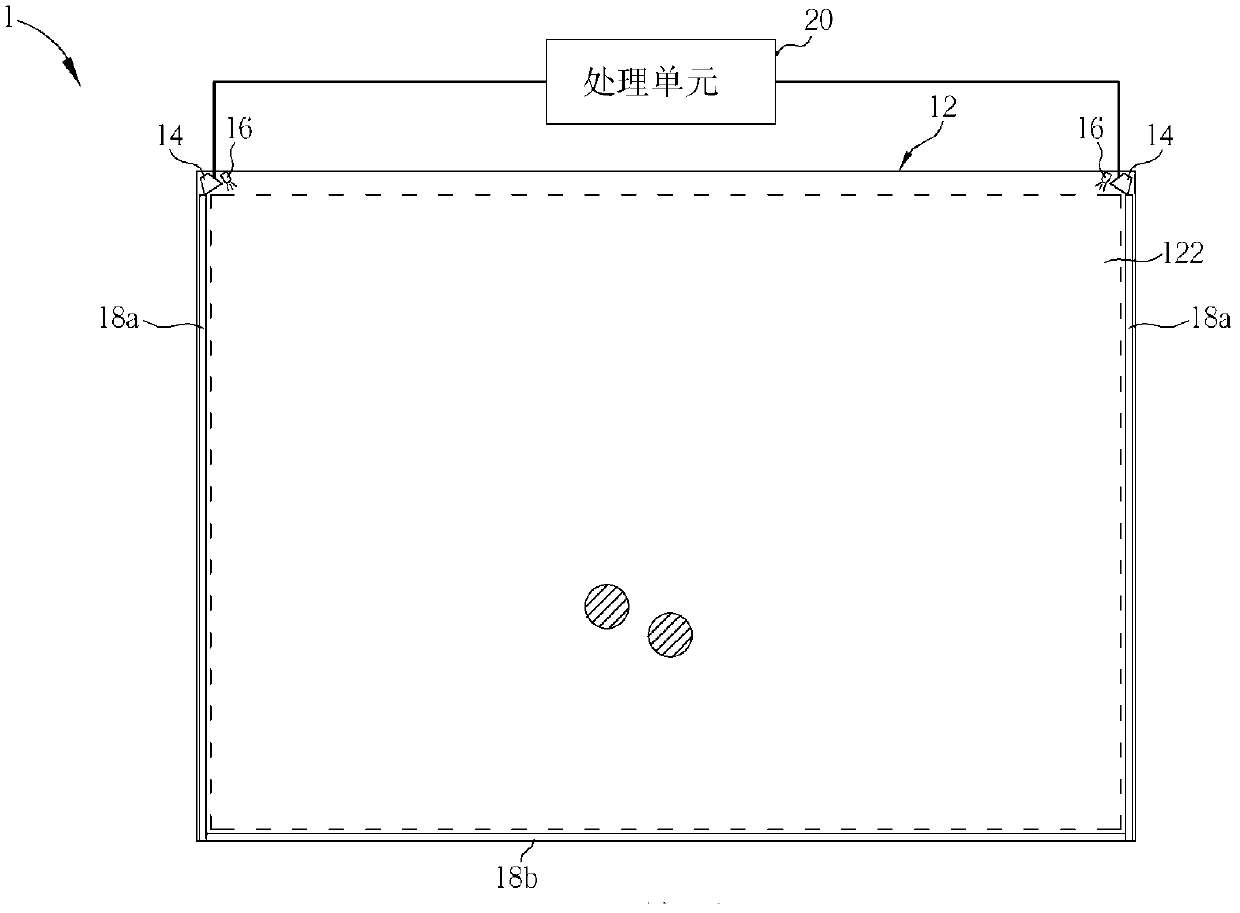
[0043] see figure 1 , which is a schematic diagram of an object detection system 1 according to a preferred embodiment of the present invention. The object detection system 1 of the present invention is used for detecting the position of at least one object. The object detection system 1 includes a frame component 12 , two camera units 14 , two light sources 16 , three reflective components 18 a, 18 b and a processing unit 20 . The frame member 12 has an indication area 122, and the object implements an indication operation in the indication area 122, wherein figure 1The hatched circles are two examples of the object performing operations in the indication area 122 ; in this embodiment, the indication area 122 is roughly rectangular, but the invention is not limited thereto. The camera unit 14 is disposed near two corners of the same side outside the indication area 122 , and the reflective members 18 a, 18 b are disposed on the other sides of the indication area 122 . The ...


PUM


Abstract

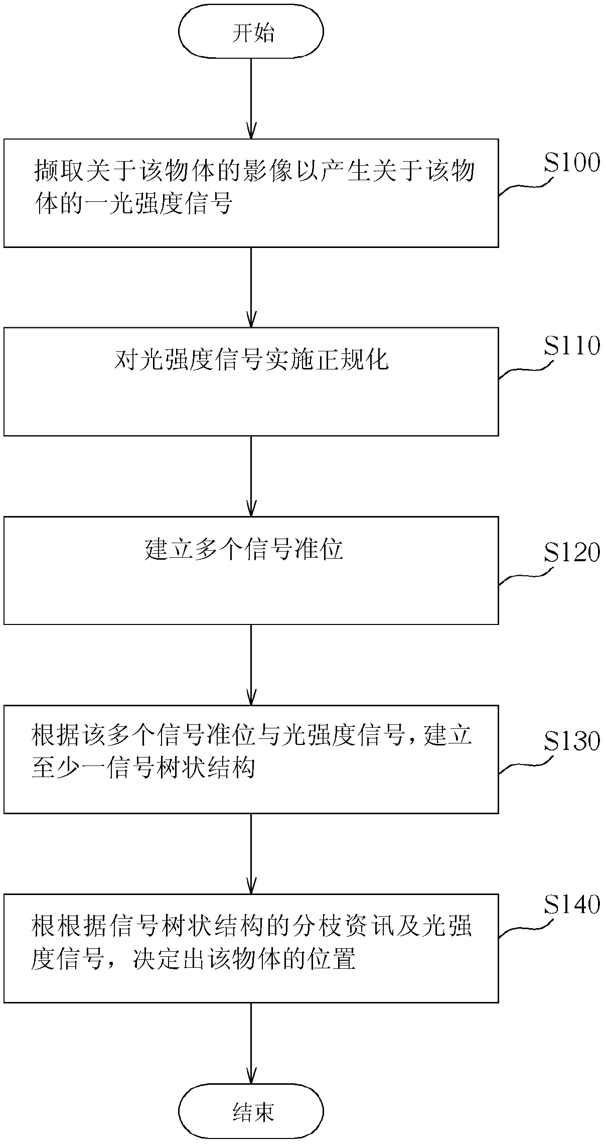
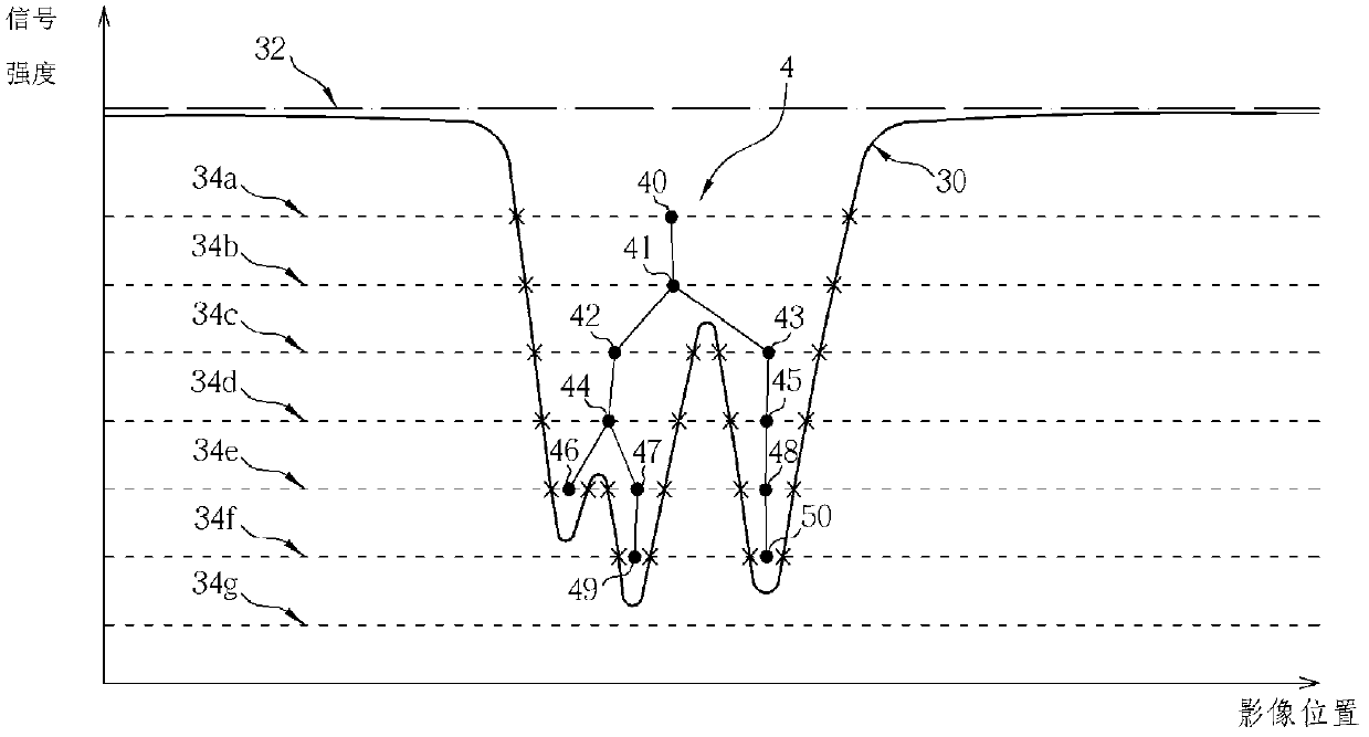
The invention relates to an object detection method and an object detection system. The technical problem to be solved by the present invention is to provide an object detection method for detecting the position of at least one object, which includes the following steps: (a) generating a light intensity signal about the object; (b) establishing a plurality of signals (c) establish at least one signal tree structure according to the plurality of signal levels and the light intensity signal; and (d) determine the signal tree structure according to the branch information of the signal tree structure and the light intensity signal Location. The purpose of the present invention is to detect the position of at least one object.

Description

technical field [0001] The present invention relates to an object detection method and an object detection system, in particular to an object detection method and an object detection system for distinguishing object positions based on tree analysis. Background technique [0002] At present, various multi-touch technologies have been widely used in various electronic devices that provide touch operations. In the multi-touch technology that uses optical images as the basis for determining the touch position, it uses optical images to establish possible light paths. The touch position is determined by the triangulation method, and it is obvious that the quality of the optical image greatly affects the judgment of the touch position. Therefore, when the light source, light transmission medium or image capture lens is not in an ideal state, it is easy to cause defects such as irregular changes in background light intensity and image capture distortion. A lot of noise makes it di...

Claims


Application Information

Patent Timeline
Patent Type & Authority Patents(China)
IPC IPC(8): G06F3/03G06F3/042
Inventor 李德原
Owner QISDA SUZHOU
Learn More