Eureka AIR delivers breakthrough ideas for toughest innovation challenges, trusted by R&D personnel around the world.

flexible cooling pipe

A duct and heat sink technology, applied in the field of flexible heat radiating ducts, can solve the problems of uneven heat dissipation of the junction surface, not meeting the needs of industrial utilization, affecting the value of industrial utilization, etc., and achieving the effect of uniform heat dissipation temperature

Inactive Publication Date: 2011-12-28
侯宗志 +2
View PDF7 Cites 9 Cited by
  • Summary
  • Abstract
  • Description
  • Claims
  • Application Information

AI Technical Summary

Problems solved by technology

[0002] Press, electronic loads generated by high heat energy such as existing integrated circuits, power transistors, chipsets, and light-emitting diode (LED) lamps need to use radiators or heat dissipation mechanisms in order to operate normally. Existing electronic loads are passive The heat dissipation fins or the air cooling method of the heat sink are not enough. In addition to the slow heat dissipation speed, the cooling efficiency of the heat source or hot spot is also very poor, and the heat dissipation temperature of each point on the interface between the electronic load and the heat sink is uneven. It does not meet the needs of industrial utilization, and is gradually eliminated
[0003] There may be improved ones because of this, and metal pipes are used to inject cooling liquid or heat dissipation liquid into the pipe, and then connect the heat sink to provide heat dissipation for the above-mentioned electronic loads. However, due to the slow flow rate of cooling liquid or heat dissipation liquid, if only heat Convection pushes the coolant or heat dissipation fluid, which cannot achieve rapid heat dissipation at all, and will limit the installation direction of the electronic load. For example, the installation direction of the LED lamp is above the radiator, that is, when the projected light is upward, if only relying on heat It is difficult to push up the cooling liquid or heat dissipation liquid to flow smoothly and quickly in the convection method. Therefore, it is usually necessary to add a small electric pump to pressurize the cooling liquid or heat dissipation liquid. However, this method will inevitably make the small electric pump It consumes extra power and equipment costs, which is not economical, and also requires space for installation, which limits its application range
[0004] The above-mentioned existing metal pipeline is equipped with an electronic load to provide a heat dissipation mechanism. Another disadvantage is that if the metal pipeline needs to be matched with the installation occasion or mechanism design of the electronic load, for example, if it is arranged in a narrow case, then It cannot be arranged smoothly, thus affecting its industrial utilization value. Moreover, the metal pipeline will be limited by the bending angle limit and deformation limit of the metal pipeline in terms of bending angle and configuration path, and cannot be applied to various shapes. In the structure of electronic products and component configuration positions, such as the metal pipeline must bypass or avoid certain mechanisms or electronic components, and must be bent or coiled in a large scale, the heat dissipation of the existing metal pipeline configuration cannot be applied, thus limiting the scope of its application
[0005] In terms of relevant previous patent technical documents, such as the invention patent case of "Liquid Cooling System" in Taiwan Patent Publication No. I265772, it discloses a typical existing metal pipeline configuration liquid cooling system. Similarly, metal pipelines will be produced. Problems and shortcomings of poor heat dissipation efficiency and bending of metal pipelines that are easily hindered by mechanism space, shape, and electronic component placement
[0006] In addition, such as China Taiwan Patent Publication No. 553602 "Radiator Improvement Structure" patent case, it discloses that a radiator composed of a small pump and a flexible heat dissipation pipe is provided to the electronic load for heat dissipation. Although it can improve the above-mentioned problem of bending configuration of metal pipelines, it still cannot solve the problem of slow flow rate of coolant or cooling fluid, and must rely on small pumps for pressurized delivery, which must consume extra power and increase equipment costs, which is not economical.
[0007] From the above, the existing heat dissipation device of the electronic load relies on the poor heat dissipation speed and efficiency of the air cooling method and the uneven heat dissipation of the junction. The installation position of the load is limited. In addition, if a small electric pump is to be added to pressurize and push the cooling fluid to circulate and dissipate heat, it will consume extra power, increase the cost and occupy the installation space.

Method used


Image

  • flexible cooling pipe
  • flexible cooling pipe
  • flexible cooling pipe

Examples


Embodiment Construction

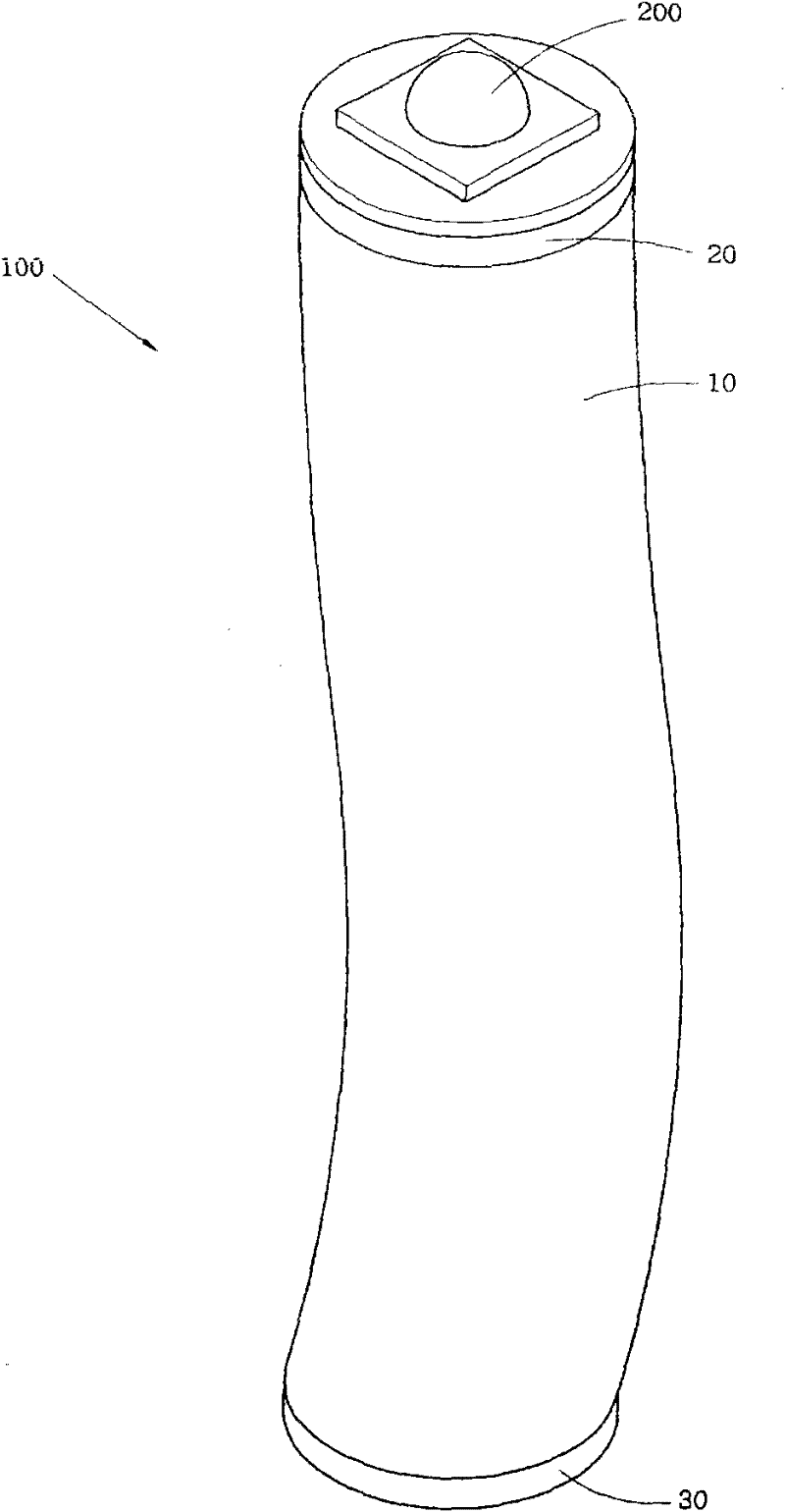
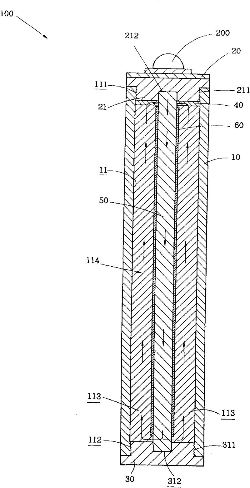
[0050] See figure 1 , figure 2 and image 3 Shown here is the first embodiment of the flexible heat dissipation pipe 100 of the present invention. The flexible heat dissipation pipe 100 includes an outer tube 10, which is a heat conductor and a flexible tube. For example: a soft silicone tube, which can be flexibly bent, the outer tube 10 forms at least one chamber 11, the inner wall of the upper end of the chamber 11 is provided with a plurality of locking screws 111, and the inner wall of the lower end of the chamber 11 is provided with A number of lock screws 112.

[0051] A heat-conducting element 20 is made of a heat-conducting material, such as metal materials such as aluminum, copper or alloy, and can be connected to an electronic load 200 on the external surface. The type of the electronic load 200 is not limited. In the present invention, a light-emitting diode lamp is used. As an example, the heat-conducting member 20 has a joint 21 formed on the inner edge, and a plur...


PUM


Abstract

A flexible heat dissipation conduit includes an outer tube, a heat conduction element, a heat dissipation element, at least one soaking ring, at least one liquid suction conduit and at least one inner tube, wherein the outer tube is a flexible tube, At least one chamber is formed inside, the heat conduction element and the heat dissipation element are respectively combined at both ends of the outer tube, the heat conduction element connects the electronic load to the surface, the heat soaking ring is connected to the inner edge of the heat conduction element, the inner pipe and the liquid suction conduit It is accommodated in the chamber of the outer tube, and the liquid suction conduit is covered by the inner pipe, and the two ends are respectively combined with the heat conduction element and the heat dissipation element, and the chamber between the inner pipe and the outer pipe is partitioned to form at least one circulation pipe. The circulation pipe is filled with at least one fluid heat transfer medium, so that the heat energy generated by the load heat source is absorbed by the heat conduction element, and the fluid heat conduction medium between the heat conduction element and the soaking ring is heated, so that the fluid heat conduction medium conducts along the liquid suction conduit by capillary action After the heat dissipation element cools down, the heat dissipation element circulates back to the soaking ring at the end of the heat conduction element through the circulation pipeline.

Description

Technical field [0001] The invention relates to a flexible heat dissipation pipe, in particular to a flexible heat dissipation pipe which utilizes at least one liquid suction pipe inside to conduct heat dissipation of at least one fluid heat transfer medium by capillary action and non-directional restricted circulation. Background technique [0002] According to the existing electronic loads that generate high heat energy such as integrated circuits, power transistors, chipsets, light-emitting diode (LED) lamps, etc., they need to use a radiator or heat dissipation mechanism in order to operate normally. The existing electronic loads are passive The cooling fins or the air cooling method of the radiator is not sufficient. In addition to the slow heat dissipation speed, the cooling efficiency of the heat source or hot spot is also very poor, and the heat dissipation temperature of each point on the interface between the electronic load and the radiator is uneven. It does not meet ...

Claims


Application Information

Patent Timeline
IPC IPC(8): H05K7/20H01L23/427
Inventor 侯宗志陈良文陈良才
Owner 侯宗志
Why Eureka
Eureka Blog
Learn More