
Instrument and method for measuring secondary clamping deviation during numerical control machining based on image technology

A technology of secondary clamping and deviation measurement, applied in measuring devices, metal processing equipment, measuring/indicating equipment, etc., it can solve the problem that the operator's technical level is also very high, the efficiency and accuracy are reduced, and the deviation value error is very large, etc. problems, to achieve the effect of fast and accurate measurement methods, improve processing accuracy and processing efficiency, and maintain continuity

Inactive Publication Date: 2011-09-14
HARBIN UNIV OF SCI & TECH
View PDF4 Cites 16 Cited by
  • Summary
  • Abstract
  • Description
  • Claims
  • Application Information

AI Technical Summary

Problems solved by technology

The edge finder tool setting method is an effective method, but it requires that the workpiece must be a good conductor, and the zero must be reset after the tool is changed. If the zero point is machined out, indirect tool setting is required, and the efficiency and accuracy will be greatly reduced. Decline; the dial gauge tool setting method is to measure the positioning pins separately, and calculate and adjust the position of the tool starting point through the measured data to complete the tool setting and processing. The existing method estimates The error of the deviation value is very large, and the workload is large, it takes a lot of man-hours, the work efficiency is low, and the requirements for the operator's technical level are also very high, which is relatively backward

Method used


Image

  • Instrument and method for measuring secondary clamping deviation during numerical control machining based on image technology
  • Instrument and method for measuring secondary clamping deviation during numerical control machining based on image technology
  • Instrument and method for measuring secondary clamping deviation during numerical control machining based on image technology

Examples


Embodiment 1

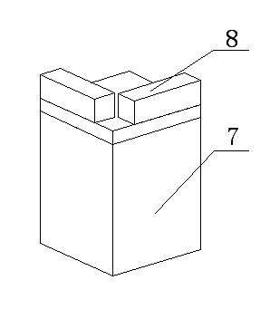
[0027] An installation method of a secondary clamping deviation measuring instrument for NC machining based on image technology. The measuring instrument is divided into two parts: the first part is composed of a camera and a digital signal processor DSP, and the second part is the shooting object. The shooting object is specially made The special measuring target, the base material of the special measuring target is 45 steel, and the upper surface is equipped with a red light-emitting diode LED lamp tube; Carve out an accurate reticle for shooting and measurement. The size of the red rectangular frame is 10.00mm×10.00mm; one X and one Y-direction level are installed on the reticle layer.

Embodiment 2

[0029] A measurement method of a secondary clamping deviation measuring instrument for NC machining based on image technology, the specific measurement method is as follows:

[0030] After installing the fixture and workpiece for the first time, install the camera on the main shaft through the tool system matching the main shaft of the machine tool to ensure a high coaxiality between the camera and the tool holder; operate the machine tool to move the camera to the origin of the processing program, that is, special measurement Directly above the target, adjust the Z-axis coordinates to H, record the X and Y-axis coordinates, and shoot; use the image processing method described below to process the captured images, and at the same time perform system calibration, measure and calculate the distance between the center of the cross and the center of the image For the actual deviation value, input the deviation value into the machine tool system, and adjust the position of the camer...

Embodiment 3

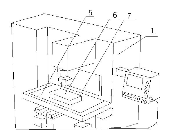
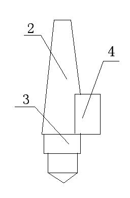
[0034] An image technology-based CNC machining secondary clamping deviation measuring instrument, which consists of: a bed body 1, the bed body 1 is equipped with a fixed handle 2, and the fixed handle 2 is connected to a camera 3 and an image processor DSP4 , the bed body 1 has a workbench 5, a workpiece holder 6 is placed on the workbench 5, a special measurement target 7 is placed on the workpiece holder, and the special measurement target 7 is connected to a horizontal Foot 8.


PUM


Abstract

The invention discloses an instrument and a method for measuring secondary clamping deviation during numerical control machining based on an image technology. A large-scale automobile covering mold is generally required to be subjected to heat treatment during actual machining, and a fixture is not separated from a workpiece during heat treatment, so positioning deviation can be generated on the X-axis and the Y-axis when the fixture and the workpiece are arranged on an operating platform of a machine tool again. The measuring instrument is divided into two parts, wherein a first part consists of a camera and a digital signal processor (DSP); a second part is a shot object; a special measuring target which is specially manufactured is used as the shot object; a base of the special measuring target is made of 45 steel; a red light emitting diode (LED) tube is arranged on the upper surface of the special measuring target; a scribed line layer is made of transparent toughened glass; a black shading coating is coated on the upper surface of the transparent toughened glass; an accurate scribed line is carved on the coating and is used for shooting and measuring; the size of a red rectangular frame is 10.00*10.00 mm; and an X-directional horizontal ruler and a Y-directional horizontal ruler are arranged on the scribed line layer respectively. The instrument and the method are used for measuring the secondary clamping deviation during numerical control machining.

Description

Technical field: [0001] The invention relates to a device for measuring the deviation of secondary clamping of numerical control machining, in particular to a measuring instrument for measuring the deviation of secondary clamping of numerical control machining based on image technology and an installation and measurement method. Background technique: [0002] In the actual processing of large-scale automobile covering molds, heat treatment is usually required. During heat treatment, the fixture and the workpiece are not separated. In this way, when the fixture and workpiece are installed on the machine tool table again, there will be positioning deviation on the X and Y axes. Therefore, the two parts of the workpiece are eliminated. The deviation caused by the secondary clamping is the key issue to improve the quality of the mold. At present, domestic methods mainly adopt manual measurement to eliminate positioning deviation, such as edge finder tool setting method and dial ...

Claims


Application Information

Patent Timeline
Patent Type & Authority Applications(China)
IPC IPC(8): B23Q17/00G01B11/00
Inventor 刘献礼宋笑然王义文杨华为张辉刘雪松
Owner HARBIN UNIV OF SCI & TECH
Learn More