
Multifunctional microfluid control device for operating biochemical fluids in microfluid control chip automatically

A technology of microfluidic chip and microfluidic device, which is applied in the direction of biological testing, material inspection, etc., can solve the problems of high cost, dead volume, low conductivity, etc., and achieve the effect of small error range and strong adaptability

Inactive Publication Date: 2011-09-07
SHANDONG NORMAL UNIV
View PDF7 Cites 5 Cited by
  • Summary
  • Abstract
  • Description
  • Claims
  • Application Information

AI Technical Summary

Problems solved by technology

The disadvantages are: due to the inclusion of micro-movable parts, the difficulty of chip processing and high cost, the performance of the micro-valve is relatively poor, there are many problems such as low back pressure, leakage and dead volume, and the application effect is not satisfactory.
Its disadvantages are: the chip structure is complex, the driving force is small, and it is suitable for low conductivity (10 -12 -10 -6 s / m) fluid
The disadvantages are: due to the relatively difficult optical focusing and the "dispersion" of the magnetic field, the device preparation is complicated, and the driving mechanism remains to be further studied
The problem now is that due to the large differences in the flow characteristics of various biological fluids (such as cell fluids), chemical fluids, and between biological fluids and chemical fluids, the existing microfluidic manipulation technology is applied to biochemical analysis of microfluidic chips. Also there are following deficiencies: 1) the driving mode is single, and some of them (as optical drive, magnetic drive) just emphasize the special application of driving, and the versatility is not strong; 2) a small amount of combination drives also only have two kinds of driving modes, for example: (gravity ) Hydraulic drive-electric drive, and the equipment that constitutes the combined drive is mostly a simple combination of individual instruments, which has shortcomings such as inconsistent control response time and affecting the reproducibility of chip analysis

Method used


Image

  • Multifunctional microfluid control device for operating biochemical fluids in microfluid control chip automatically
  • Multifunctional microfluid control device for operating biochemical fluids in microfluid control chip automatically
  • Multifunctional microfluid control device for operating biochemical fluids in microfluid control chip automatically

Examples


Embodiment 1

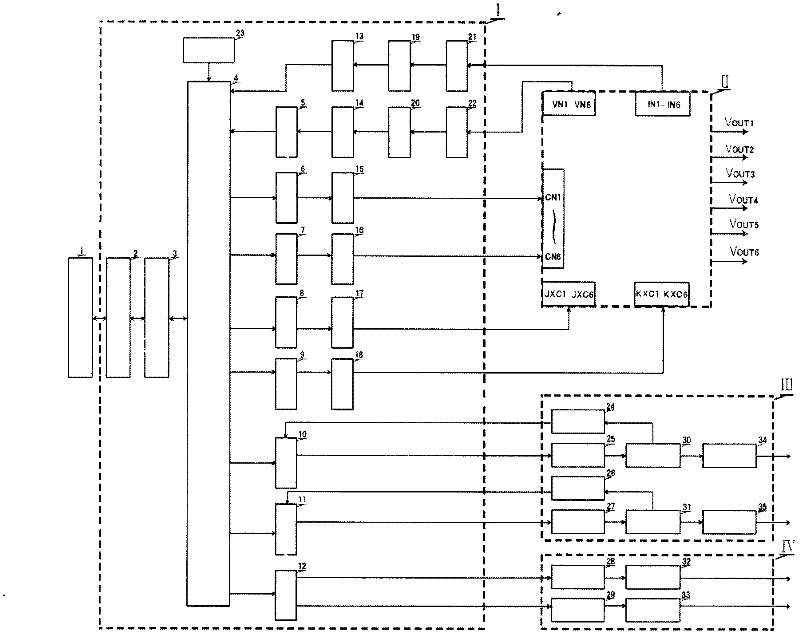
[0057] It consists of a system control module I, an electric drive module II, a hydraulic drive module III, a dielectrophoresis module IV and program software, wherein: the system control module I uses a single-chip microprocessor 4 as the control core, and the The electric drive module II is a six-way DC high voltage, the hydraulic drive module III is a two-way micro-injection pump, the dielectrophoresis module IV is a two-way sine wave, and the program software is controlled by a time period.

[0058] The single-chip microprocessor 4:

[0059] Connect to the serial port of PC 1 through logic level conversion 3 and digital communication interface 2; connect to the input terminals of two parallel analog signal conditioning circuits 15 and 16 through two parallel digital-to-analog conversion circuits 6 and 7 respectively ; Through two parallel serial shift registers 8,9 are respectively connected with the input terminals of two parallel power expansion circuits 17,18; the outpu...

Embodiment 2

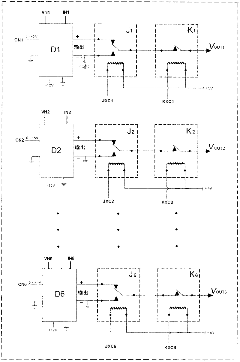
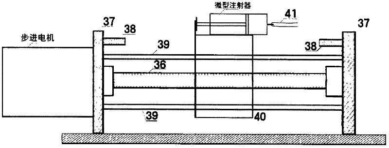
[0070] combined with figure 1 , 2 , 3 further describe in detail the combined connection between each module of the present invention and each device in each module:

[0071]PC machine 1 is the PC machine that program software of the present invention has been installed, and PC machine is responsible for functions such as data collection, storage, display / record, single-chip microprocessor management and interface operation. The digital communication interface 2 and the logic level conversion 3 are used for two-way data communication between the PC and the single-chip microprocessor 4 . The single-chip microprocessor is an enhanced micro-power consumption 8-bit single-chip microprocessor ATmega16-16PC produced by ATMEL. The ATmega16-16PC has 16K bytes of programmable Flash, 512 bytes of EEPROM, 1K bytes of SRAM, and 32 1 general-purpose I / O ports, 32 general-purpose working registers, 3 timers / counters (T / C), on-chip / external interrupts, UART serial communication ports (TXD,...

Embodiment 3

[0079] Embodiment 3: Further describe the working process of the present invention applied to microfluidic chip biochemical analysis:


PUM


Abstract

The invention provides a multifunctional microfluid control device for operating biochemical fluids in a microfluid control chip automatically. The device consists of a system control module, electric drivers of six paths of direct-current high voltages, hydraulic drivers of two paths of micro-injection pumps, dielectrophoretic devices of two paths of sine waves and program software. The multifunctional microfluid control device has the characteristics that: through arbitrary combination of six paths of the direct-current high voltages (disconnection, voltage / connection and grounding), two paths of the micro-injection pumps (front waiting, propelling / injection, back waiting and withdrawal) and two paths of the sine waves (front waiting, sine wave and back waiting), independent or / and synchronous programmable control, rapid switching and stable output, the automatic operation on different biochemical fluids in the microfluid control chips with different structures is facilitated; and biochemical analysis on the microfluid control chip with strong establishing adaptability and small error range is more flexible and more simple and convenient.

Description

Technical field: [0001] The invention belongs to the microfluidic instrument platform technology, and in particular relates to a multifunctional microfluidic device for automatically manipulating the biochemical fluid of a microfluidic chip, which integrates electric drive, hydraulic drive, dielectrophoresis and fully automatic control. Background technique: [0002] Microfluidic chip (microfluidic chip) has become an important platform for microanalysis research in the fields of biology and chemistry in recent years because of its advantages of low consumption, rapidity, and integration of various analysis functions. Since microfluidic chip analysis is carried out in a micron-scale separation and analysis channel with network characteristics on a chip of a few square centimeters, the sample preparation and injection involved in biochemical experiments can be realized through the rapid manipulation of nanoliter or even picoliter sample scale. , mixing, reaction, separation, ...

Claims


Application Information

Patent Timeline
IPC IPC(8): G01N33/50
Inventor 李清岭唐波陈蓁蓁
Owner SHANDONG NORMAL UNIV
Learn More