Electric contact for vacuum valve and vacuum interrupter using the same
An electrical contact and vacuum valve technology, which is applied to high-voltage air circuit breakers, circuits, contacts, etc., can solve the problems of insufficient sintering, failure of electrical contacts to obtain energization performance and circuit breaking performance, and damage to the soundness of brazing parts.
- Summary
- Abstract
- Description
- Claims
- Application Information
AI Technical Summary
Problems solved by technology
Method used
Image

Examples
Embodiment 1
[0035] In this example, a sintered body composed of raw materials of the electrical contact 1 having the composition shown in Table 1 was fabricated.
[0036] The manufacturing method of the electrical contact 1 will be described below. First, a powder of a ternary intermetallic compound is prepared. In this example, to become 48.2Cu 2 Te-51.8Cr 2 Te 3 (wt%) mixed Cu in a mortar 2 Te and Cr 2 Te 3 Powder (with a particle size of 10 μm or less) is filled into a mold, pressurized at a pressure of 294 MPa, and then heated at 800°C for 1 hour in a vacuum to synthesize Cr 2 CuTe 4 . Crush it with a mortar to produce Cr with a particle size of 50 μm or less 2 CuTe 4 powder. Next, Cr powder with a particle size of 80 μm or less, Cu powder with a particle size of 60 μm or less, the above-mentioned Cr 2 CuTe 4 The powder was mixed with a V-shaped mixer with the composition shown in Table 1, and the mixed powder was filled into a mold, and press-molded at a pressure of 294 ...
Embodiment 2
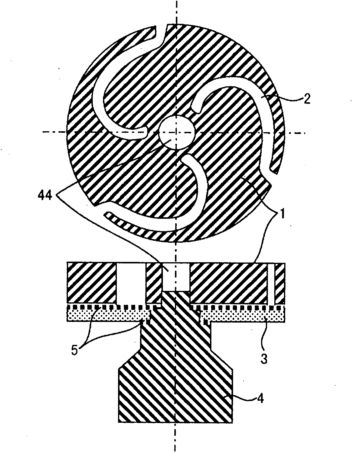
[0045] figure 1 It is a sectional view showing the structure of an electrode. exist figure 1 Among them, 1 is an electric contact, 2 is a slot for driving the arc, 3 is a stainless steel reinforcing plate, 4 is an electrode rod, 5 is solder, and 44 is for preventing the arc from stagnating at the center of the electric contact 1. the central hole.
[0046] Carry out mechanical processing to the sintered body obtained in the embodiment, make figure 1 Electrical contacts 1 of the shape shown. In addition, the electrical contact 1 can also be obtained by filling the mixed powder into a mold that can form the final shape with the slot 2 and the central hole 44, and the electrical contact 1 can also be obtained by sintering. In this method, since subsequent processing such as machining is not required, the , which can be easily produced.
[0047] The fabrication method of the electrodes is as follows. Through machining in advance, the electrode rod 4 is made of oxygen-free co...
Embodiment 3
[0050] Using the electrode produced in Example 2, a vacuum valve was produced. The specifications of the vacuum valve are: rated voltage 7.2kV, rated current 600A, rated breaking current 20kA.
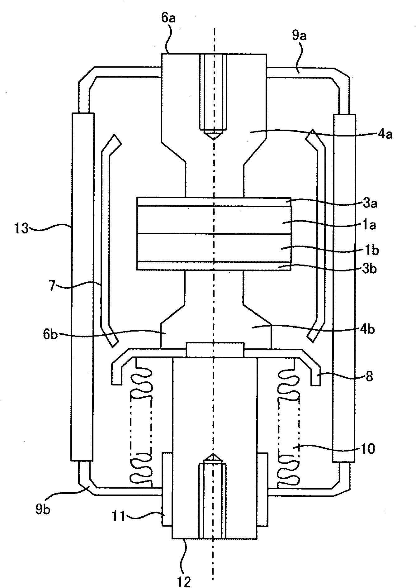
[0051] figure 2 It is a figure which shows the structure of the vacuum valve concerning this Example. exist figure 2 Among them, 1a and 1b are fixed side electric contacts and movable side electric contacts respectively, 3a and 3b are reinforcement plates, 4a and 4b are fixed side electrode rods and movable side electrode rods respectively, and they respectively constitute fixed side electrodes 6a, The movable side electrode 6b. In addition, in this embodiment, the grooves of the electrical contacts on the fixed side and the movable side are provided so as to coincide with each other on the contact surface. The movable-side electrode 6 b is soldered to the movable-side holder 12 via the movable-side shield 8 that prevents scattering of metal vapor and the like during disconnectio...
PUM
| Property | Measurement | Unit |
|---|---|---|
| Particle size | aaaaa | aaaaa |
Abstract
Description
Claims
Application Information
 - Generate Ideas
- Intellectual Property
- Life Sciences
- Materials
- Tech Scout
- Unparalleled Data Quality
- Higher Quality Content
- 60% Fewer Hallucinations
Browse by: Latest US Patents, China's latest patents, Technical Efficacy Thesaurus, Application Domain, Technology Topic, Popular Technical Reports.
© 2025 PatSnap. All rights reserved.Legal|Privacy policy|Modern Slavery Act Transparency Statement|Sitemap|About US| Contact US: help@patsnap.com