conductor connection device

A conductor connection and conductor technology, which is applied in the field of conductor connection devices, can solve the problems of reduced yield, difficulty in plating, high conductor cost, etc., and achieve the effect of preventing re-formation

Active Publication Date: 2020-10-13
MITSUBISHI ELECTRIC CORP
View PDF6 Cites 0 Cited by
  • Summary
  • Abstract
  • Description
  • Claims
  • Application Information

AI Technical Summary

Problems solved by technology

However, due to the high cost of plating the entire conductor, and the need for masking when partial plating is performed, the cost may be higher than the overall plating cost depending on the shape of the conductor
In addition, depending on the conductor material, there may be a property that plating is difficult to adhere to due to the oxide film formed on the conductor surface
Therefore, the cost of plating the conductor is high, and it also has the disadvantage that sometimes the yield of the component may be reduced due to the above-mentioned properties

Method used


Image

  • conductor connection device
  • conductor connection device
  • conductor connection device

Examples


Embodiment approach 1

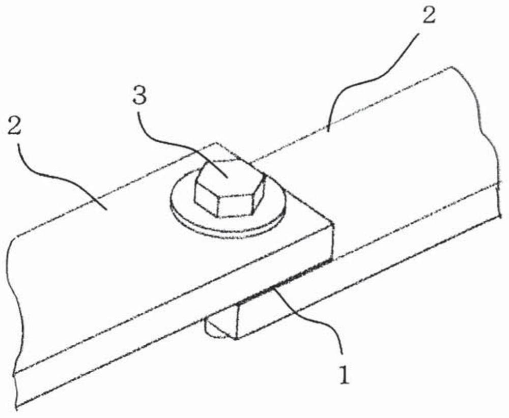
[0038] based on Figure 1 to Figure 4 The conductor connection device in Embodiment 1 will be described.

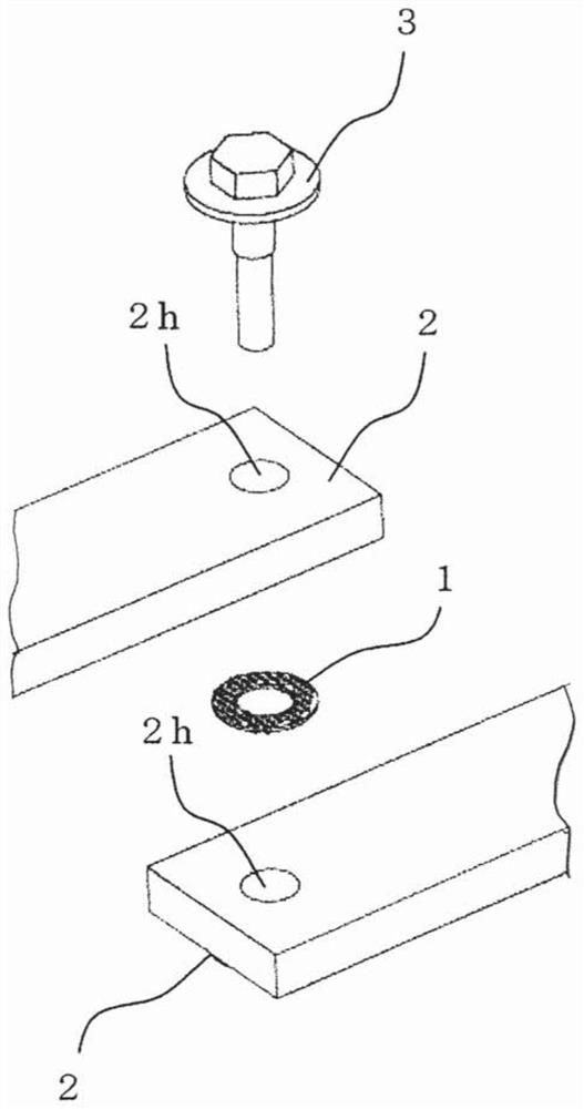
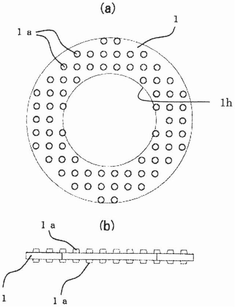
[0039] figure 1 is a perspective view of the conductor connection device, figure 2 is an exploded perspective view of the conductor connection device, image 3 (a) is a front view of a conductive member for conductor connection, image 3 (b) is a side view, Figure 4 It is an explanatory diagram showing the test results of a short-time energization test conducted to confirm the performance of the conductive member for conductor connection.

[0040] The conductor connecting device is composed of a fastener (fastening member) and a conductive member for connecting flat conductors (hereinafter referred to as “conductive member with protrusions” as appropriate) 1. Bolts 3 and nuts (not shown), the conductive member for connecting the flat conductors is inserted (sandwiched) between the two conductors when the conductors 2 are connected and fastened. Similar to the washe...

Embodiment approach 2

[0049] based on Figure 5 to Figure 7 A conductor connection device in Embodiment 2 will be described.

[0050] Figure 5 is a perspective view of the conductor connection device, Figure 6 is an exploded perspective view of the conductor connection device, Figure 7 (a) is a front view of the conductive member, Figure 7 (b) is a side view.

[0051] In Embodiment 1, a protruding conductive member 1 having a shape similar to a washer is used, but as Figure 5 As shown, in the case of fastening conductors 2 to each other with a plurality of bolts 3 , it is necessary to insert protruding conductive members 1 having a shape similar to washers according to the number of holes in the fastening portion. In contrast, in Embodiment 2, using Figure 7 Such abutting plate-shaped conductive member 4 with protrusions. Thus, if Figure 6 As shown, even if a plurality of fastening holes are opened on the conductor 2, only one conductive member 4 with a protrusion needs to be clamped...

Embodiment approach 3

[0053] based on Figure 8 to Figure 9 A conductor connection device in Embodiment 3 will be described.

[0054] Figure 8 is a perspective view of the conductor connection device, Figure 9 (a) is a front view of the conductor member, Figure 9 (b) is a side view.

[0055] In Embodiments 1 and 2, the conductors 2 are overlapped and connected. In Embodiment 3, the conductors 2 are connected to each other, and the conductors 2 are connected to each other through the abutting plate-shaped conductive member 5 with protrusions. In the case of the above-mentioned conductor connection, the conductive member 5 for connecting the conductor 2 is connected to the surface of the conductor 2 in the same direction, so that the protrusion 5a of the conductive member 5 abutting on the plate-shaped band protrusion is only implemented on one side. Formation and coating of a conductive auxiliary coating agent are sufficient. therefore, Figure 9 The surface of the shown abutting plate-shap...


PUM


Abstract

[Problem] When conductors are connected to one another, conventionally the conductors are plated with silver or tin, which are conductive and corrosion resistant, in order to prevent the formation of oxide films on the surface of the conductors, and to prevent electrolytic corrosion resulting from different types of metal coming into contact with one another. Plating the entire conductor results in an increase in cost, and partial plating requires the addition of a masking operation, and depending on the shape of the conductor, may result in a cost that is higher than coating the entire conductor. [Solution] According to the present invention, when conductors are to be connected using a fastener, an electrically conductive member for connection of conductors is interposed between the two conductors. A plurality of protruding portions are formed on the surfaces, of the electrically conductive member for connection of conductors, that come into contact with the conductors. A plating layer is formed on the contacting surfaces that include the protruding portions, by means of an electrically conductive and corrosion-resistant plating process. When the conductors are connected to one another using a fastener, the contact pressure of the protruding portions causes oxide films on the electrically conductive member for connection of conductors to be removed.

Description

technical field [0001] The present invention relates to conductor connection, in particular to a conductor connection device installed in a metal-enclosed switchgear for supplying power to power stations, substations, factories and the like. Background technique [0002] The metal-enclosed switchgear that constitutes the existing power distribution equipment is configured as follows Figure 15 The main bus conductor 9 and the branch bus conductor 10 shown are conductors for supplying current, and their function is to obtain power from the outside or supply power to loads through these conductors. The electric power obtained from the external cable 11 used to introduce electric power flows through the branch bus conductor 10, and flows to the main bus through a switching device such as a circuit breaker for blocking current, a current transformer or a measuring transformer such as a zero-phase current transformer. Conductor 9. The power flowing through the main bus conductor...

Claims


Application Information

Patent Timeline
Patent Type & Authority Patents(China)
IPC IPC(8): H01R4/58H01R4/34
CPCH01R4/304H01R4/34H01R4/58
Inventor 佐佐木贵浩山地徹滨田达哉小鹤进永易信和木村俊则
Owner MITSUBISHI ELECTRIC CORP
Why Eureka
Try Eureka