Container tilting concentrator

A tilting, concentrator technology, applied in laboratory containers, laboratory utensils, chemical instruments and methods, etc., can solve the problems of complicated work content, air pollution, reducing concentration efficiency, etc., and is conducive to rapid heating , save energy consumption, expand the effect of contact area

Inactive Publication Date: 2011-03-23
BEIJING POLYTECH INSTR
View PDF1 Cites 10 Cited by
  • Summary
  • Abstract
  • Description
  • Claims
  • Application Information

AI Technical Summary

Problems solved by technology

[0007] 2) The work content is complicated
[0008] 3) After the chemical reagents in the test tube evaporate, harmful gases will be formed. If they are discharged into the laboratory, they will cause harm to the health of operators, etc.; if they are discharged into the atmosphere, they will cause air pollution, which is not conducive to environmental protection.
The efficiency of evaporative concentration will decrease
[0012] 2) After heating in a water bath, water mist or water vapor will form around the test tube and the gas jet, and even condense on the wall of the test tube, which will not only pollute the sample, even cross-contaminate, but also reduce the concentration efficiency
[0013] 3) After the chemical reagents in the test tube evaporate, harmful gases will be formed. If they are discharged into the laboratory, they will cause harm to the health of operators, etc.; if they are discharged into the atmosphere, they will cause air pollution, which is not conducive to environmental protection.

Method used


Image

  • Container tilting concentrator
  • Container tilting concentrator
  • Container tilting concentrator

Examples


Embodiment 1

[0051] figure 1 It is a schematic diagram of the front view of Embodiment 1 of the container inclined concentrator of the present invention; figure 2 It is a top view schematic diagram of Embodiment 1 of the container inclined concentrator of the present invention; image 3 It is a schematic side view of Embodiment 1 of the container inclined concentrator of the present invention; Figure 4 is along figure 1 A schematic cross-sectional view of the A-A line. As shown in the figure, a container inclined concentrator proposed by the present invention has a closed container, and the closed container includes a housing 1 and a cover 2 capable of sealingly covering the housing. 1 is provided with an evaporation chamber 10, and the evaporation chamber 10 is provided with a container placement rack 3. The casing 1 is provided with an exhaust port 11, and the cover body 2 is provided with multiple rows of spray pipes 20. The positions and structures of the exhaust ports and the sp...

Embodiment 2

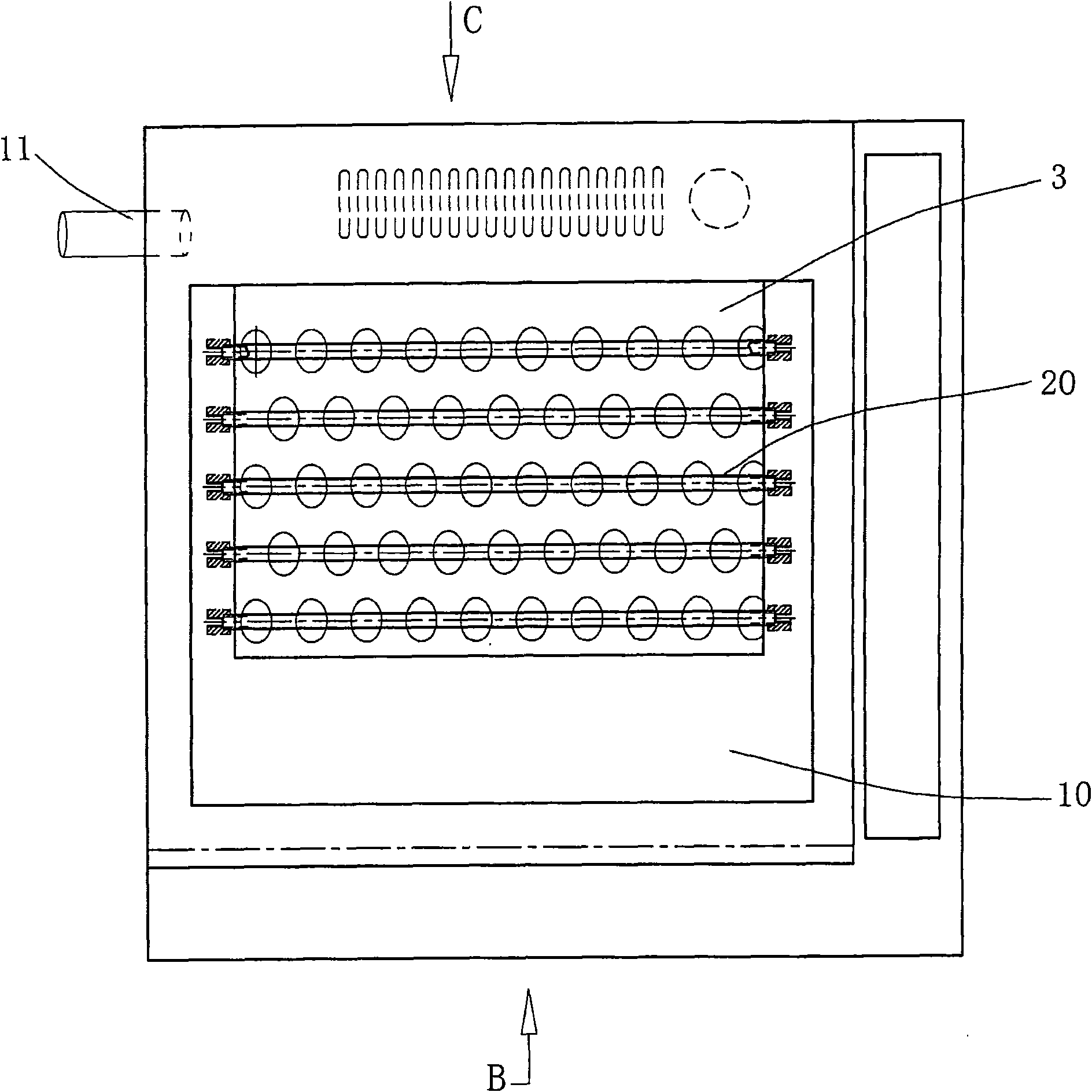
[0063] Figure 9 It is a schematic front view of Embodiment 2 of the container inclined concentrator of the present invention; Figure 10 It is a schematic top view of Embodiment 2 of the container inclined concentrator of the present invention; Figure 11 It is a schematic side view of Embodiment 2 of the container inclined concentrator of the present invention; Figure 12 is along Figure 9 Schematic cross-sectional view of line B-B in middle.

[0064] As shown in the figure, in this embodiment, the exhaust port 11 is connected to a reagent recovery device 5 . The reagent recovery device 5 and the airtight container composed of the housing 1 and the cover 2 can be provided separately or integrally. Such as Figure 9 , 10 , Shown in 12, have represented the structure that is arranged as a whole. Wherein, the reagent recovery device 5 is arranged on one side of the evaporation chamber 10 in the casing, and an exhaust fan 51 arranged in the casing transports the evaporat...

Embodiment 3

[0068] In order to facilitate the evaporation of reagents, infrared heaters or microwave heaters (not shown) may be arranged around and on the bottom surface of the evaporation chamber 10 . Alternatively, an electromagnetic heater or a heating sheet may also be provided on the bottom surface of the evaporation chamber. Wherein, the heating sheet is a sheet-shaped resistance wire heater.

[0069] The use of infrared heating, electromagnetic heating or microwave heating is more conducive to the rapid heating of the evaporation environment. Among them, infrared heating and microwave heating can make the environment in the evaporation chamber reach the preset temperature in a very short time, thereby saving energy consumption. .

[0070] Other structures, working principles and beneficial effects of this embodiment are the same as those of Embodiments 1 and 2, and will not be repeated here.


PUM

PropertyMeasurementUnit
angleaaaaaaaaaa

Abstract

The invention relates to a container tilting concentrator, which is provided with a sealed container, wherein the sealed container comprises a shell and a cover body which can be sealed and covered on the shell; an evaporating cabin is arranged in the shell, and a container-placing rack is arranged in the evaporating cabin; an air exhaust port is arranged on the shell, and multirow blowpipes are arranged on the cover body. The container tilting concentrator is characterized in that the container can be arranged on the placing rack in a tilting mode, a plurality of nozzles are arranged on each blowpipe, and each nozzle corresponds to the opening of the container, is vertically close to the side wall of the container and extends into the container. By using the concentrator of the invention, the liquid reagent evaporation and concentration efficiency can be effectively improved, the emission amount of harmful gases and environmental pollution are reduced, the operation safety for the operation personnel is guaranteed, and incorrect operation can be prevented through an inductive sensor under the condition of water bath heating.

Description

technical field [0001] The invention relates to an evaporation concentration device for concentrating liquid reagents, in particular to a container tilting concentrator capable of tilting the container to effectively improve the evaporation and concentration efficiency of liquid reagents. Background technique [0002] At present, known evaporation and concentration instruments mainly use the traditional nitrogen drying method and the vortex air flow concentration method to evaporate and concentrate liquid reagents, which generally have the disadvantages of low efficiency and a large waste of required resources. In addition, the known evaporative concentrators do not have more effective measures to prevent cross-contamination of reagents, and most of the reagent vapors are directly discharged into the laboratory or outdoor atmosphere, thereby causing environmental pollution. specifically is: [0003] 1. Traditional nitrogen drying method [0004] Place the glass tube (cup) ...

Claims


Application Information

Patent Timeline
Patent Type & Authority Applications(China)
IPC IPC(8): G01N1/40B01L3/00B01D1/00
Inventor 田莉娟李东旭王洪凯
Owner BEIJING POLYTECH INSTR
Why Eureka
Try Eureka