Method and device for manufacturing battery pack
A manufacturing method and manufacturing device technology, applied in the field of battery pack manufacturing and manufacturing devices, capable of solving the problems of reduced battery capacity, damage, and low practicability of forming materials, etc.
- Summary
- Abstract
- Description
- Claims
- Application Information
AI Technical Summary
Problems solved by technology
Method used
Image

Examples
Embodiment approach 1
[0110] Embodiments of the present invention will be described below with reference to the drawings. First, for easy understanding, a battery pack manufactured by the manufacturing method and manufacturing apparatus of the present invention will be described. As an example of such a battery pack, a battery pack using a flat prismatic lithium-ion secondary battery suitable for a mobile phone power supply will be described.
[0111] Figure 9A ~ Figure 9D A part of the manufacturing process of a battery pack intermediate product in which a lithium-ion secondary battery (hereinafter referred to simply as a secondary battery) and a circuit board, which are components of a battery pack, are integrated is shown in process steps. The configuration of the secondary battery 63 shown in the illustration is that the power generation unit is accommodated in the aluminum battery can 64 composed of a bottomed cylindrical body having a flat oval cross-sectional shape.
[0112] (not shown). ...
Embodiment approach 2
[0174] Embodiment 2 of the present invention will be described below. Embodiment 2 is modified from Embodiment 1, and the differences from Embodiment 1 will be mainly described below.
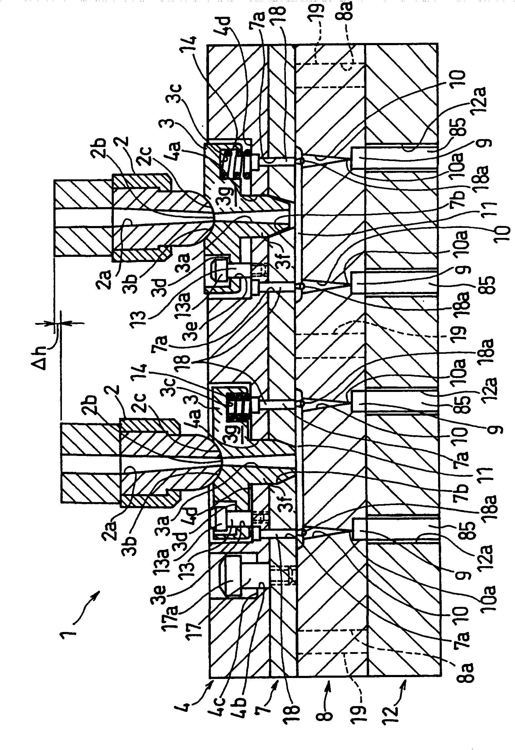
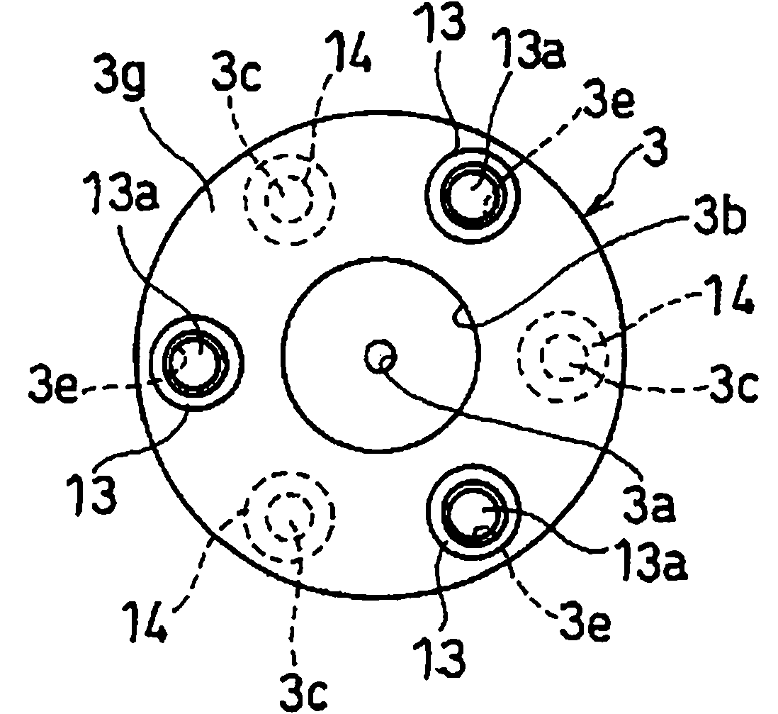
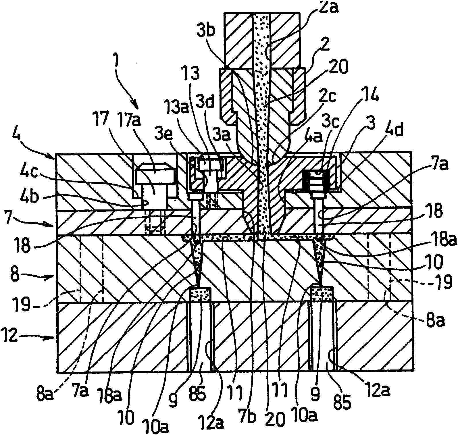
[0175] In Embodiment 2, the implementation refers to Figure 8A and Figure 8B The procedure described is to replace that in Embodiment 1 Image 6 process. That is to say, when the cured resin 23 is firmly bonded to the inner peripheral surface of the sprue 3a due to the strong adhesiveness of the molding material, even if it is used to give the cured resin 23, it will not be cut into small pieces. The above-mentioned distance d of the tensile stress may cause fracture by suddenly raising the sprue bushing 3 . Then, in the bush holder 4 from Figure 5 When the state rises, the elastic force of the push-up spring 14 is set to such an extent that the sprue bush 3 and the bush holder 4 cannot be pushed upward integrally. Thus, if Figure 8A As shown, when the bush holder 4 and the nozzle 2 ...
Embodiment approach 3
[0184] Embodiment 3 of the present invention will be described below. Embodiment 3 is modified from Embodiment 1, and the differences from Embodiment 1 will be mainly described below.
[0185] In Embodiment 3, at least one of the cavity plate 8 and the sprue bushing 3 is formed of quenched and tempered steel as the base material, and the runner 10 and the sprue 3 a are arranged inside them. The peripheral surface is formed to have a surface roughness of 10 to 100 μm by electric discharge machining.
[0186] In the runner 10, the cured resin 21 is firmly adhered to the inner peripheral surface of the runner 10 in a bonded state, so the releasability is generally poor. However, in Embodiment 3, since the inner peripheral surface of the runner 10 is formed with a surface roughness of 10 to 100 μm, the releasability of the cured resin 21 from the runner 10 is improved. As a result, even if the cured resin 21 is subjected to a strong upward pulling force by the lock portion 18 , ...
PUM
| Property | Measurement | Unit |
|---|---|---|
| roughness | aaaaa | aaaaa |
| roughness | aaaaa | aaaaa |
Abstract
Description
Claims
Application Information
 - R&D
- Intellectual Property
- Life Sciences
- Materials
- Tech Scout
- Unparalleled Data Quality
- Higher Quality Content
- 60% Fewer Hallucinations
Browse by: Latest US Patents, China's latest patents, Technical Efficacy Thesaurus, Application Domain, Technology Topic, Popular Technical Reports.
© 2025 PatSnap. All rights reserved.Legal|Privacy policy|Modern Slavery Act Transparency Statement|Sitemap|About US| Contact US: help@patsnap.com