I2-II-IV-VI4 base thin film solar battery
A thin-film solar cell, I2-II-IV-VI4 technology, applied in circuits, electrical components, photovoltaic power generation, etc., can solve the problems of low efficiency of base thin-film solar cells, unoptimized device structure, insufficient ohmic contact, etc. , to achieve the effect of improving light utilization efficiency, improving charge collection capacity, and high photoelectric conversion efficiency
- Summary
- Abstract
- Description
- Claims
- Application Information
AI Technical Summary
Problems solved by technology
Method used
Image

Examples
preparation example Construction
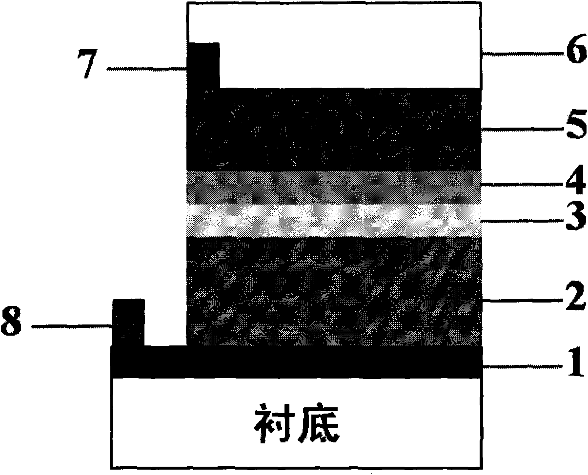
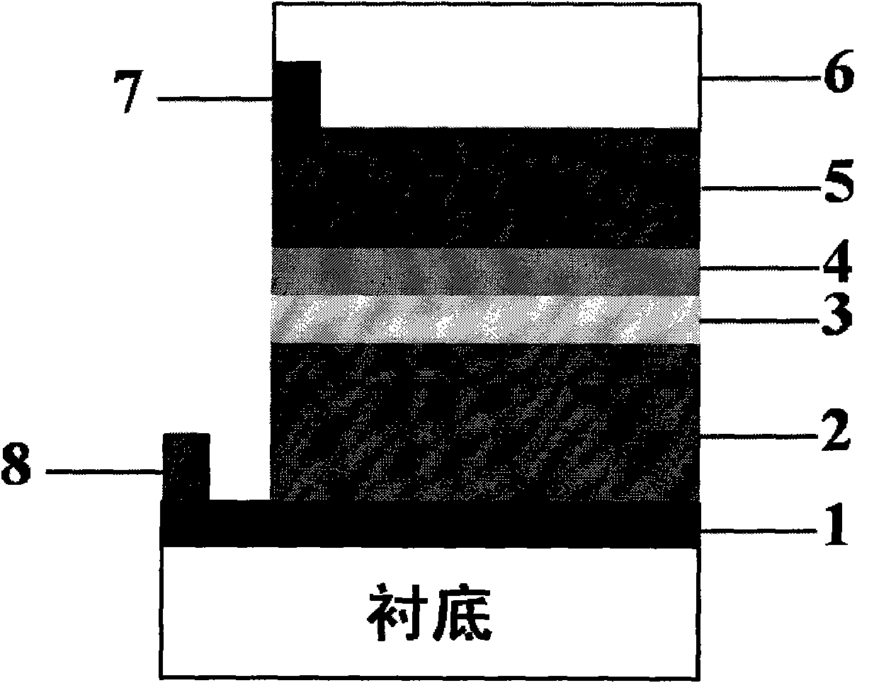
[0023] The preparation of the window layer ZnS thin film usually adopts the chemical bath deposition method, and can also adopt the sputtering method or the electron beam deposition method. The thickness of the window layer film is 50 nm to 200 nm.
[0024] The transparent conductive layer is ZnO:Al or In 2 O 3 : Sn, generally prepared by magnetron sputtering, with a thickness of 100nm to 1500nm.
[0025] The interdigitated metal electrode is a Ni / Al double-layer electrode, which is generally prepared by evaporation method, and can also be prepared by sputtering method, wherein the thickness of Ni is 5nm-50nm, and the thickness of Al is 500nm-2500nm.
[0026] Anti-reflection coating is MgF 2 , which is generally prepared by evaporation method, and can also be prepared by sputtering method, with a thickness of 50 nm to 500 nm.
Embodiment 1
[0029] Substrate: The substrate is made of ordinary soda lime glass with a thickness of 2mm.
[0030] Bottom electrode: Cu 0.5 Zn 0.5 Te / Mo bilayer composite film, prepared by magnetron sputtering method, in which the sputtering power density of Mo is 5Wcm -2 , Cu 0.5 Zn 0.5 The sputtering power density of Te is 1.5Wcm -2 , where the Mo film thickness is 800 nm, the Cu 0.5 Zn 0.5 The thickness of the Te film was 50 nm.
[0031] Light absorption layer: The light absorption layer adopts Cu 1.6 Zn 1.1 Sn 0.9 S 1.6 Se 2.4 The semiconductor thin film, the absorption layer was prepared by co-sputtering Cu, ZnS, SnS to prepare a precursor film with a thickness of 1000 nm, and then heat treatment at 570 °C for 30 min in an atmosphere of S and Se to form a Cu with a thickness of 1200 nm. 1.6 Zn 1.1 Sn 0.9 S 1.6 Se 2.4 semiconductor thin film.
[0032] Buffer layer: ZnS film with a thickness of 20 nm and SnS film with a thickness of 5 nm were prepared by sputtering on t...
Embodiment 2
[0039] Substrate: The substrate is made of ordinary soda lime glass with a thickness of 2mm.
[0040] Bottom electrode: Cu 0.6 Zn 0.4 Te / Mo bilayer composite film, prepared by magnetron sputtering method, in which the sputtering power density of Mo is 5Wcm -2 , Cu 0.6 Zn 0.4 The sputtering power density of Te is 1.5Wcm -2 , where the Mo film thickness is 1200 nm, the Cu 0.6 Zn 0.4 The thickness of the Te film was 20 nm.
[0041] Light absorption layer: The light absorption layer adopts Cu 1.6 ZnCd 0.1 Sn 0.9 S 3.2 Se 0.8 The semiconductor thin film, the absorption layer is prepared by the organic colloid solution method, the iodide of Cu, Zn, Cd, Sn is dissolved in the organic solvent of alcohol amine multifunctional group, and then anhydrous ammonium sulfide and anhydrous ammonium selenide are added to form The organic colloid source solution of Cu, Zn, Cd, Sn, S and Se was then cast to form a film, dried at 350 °C for 5 min, and heat-treated at 580 °C for 30 min ...
PUM
 Abstract
Description
Claims
Application Information
 - R&D
- Intellectual Property
- Life Sciences
- Materials
- Tech Scout
- Unparalleled Data Quality
- Higher Quality Content
- 60% Fewer Hallucinations
Browse by: Latest US Patents, China's latest patents, Technical Efficacy Thesaurus, Application Domain, Technology Topic, Popular Technical Reports.
© 2025 PatSnap. All rights reserved.Legal|Privacy policy|Modern Slavery Act Transparency Statement|Sitemap|About US| Contact US: help@patsnap.com