
Axle steel continuous casting method

A technology of axle steel and continuous casting, which is applied in the field of axle steel continuous casting, can solve the problems that the results are difficult to meet the axle steel, center porosity, and eliminate the center shrinkage and cracks of the casting billet.

Inactive Publication Date: 2010-06-16
PANGANG GROUP RESEARCH INSTITUTE CO LTD +2
View PDF0 Cites 13 Cited by
  • Summary
  • Abstract
  • Description
  • Claims
  • Application Information

AI Technical Summary

Problems solved by technology

Although the subsequent production process of the billet has undergone mechanical processing such as rolling and forging, the compression ratio is generally 3-5, and it is difficult to eliminate the shrinkage porosity and cracks in the center of the billet during the subsequent machining process. Ultrasonic flaw detection can be obtained The level and index of internal defects such as slab center segregation, center porosity, center shrinkage cavity, and center crack, as a result, it is difficult to meet the requirements of the axle steel billet standard. Therefore, the die casting process has always been the preferred way to produce axle billets
However, die casting cannot meet the needs of the rapid development of railway traffic, and the production volume is limited. Therefore, it is necessary to formulate a reasonable continuous casting method to solve the problems of central looseness, central shrinkage cavity and central crack of axle steel continuous casting slabs, which is the key to producing high-quality axle steel. key

Method used


Image

  • Axle steel continuous casting method
  • Axle steel continuous casting method
  • Axle steel continuous casting method

Examples


Embodiment approach

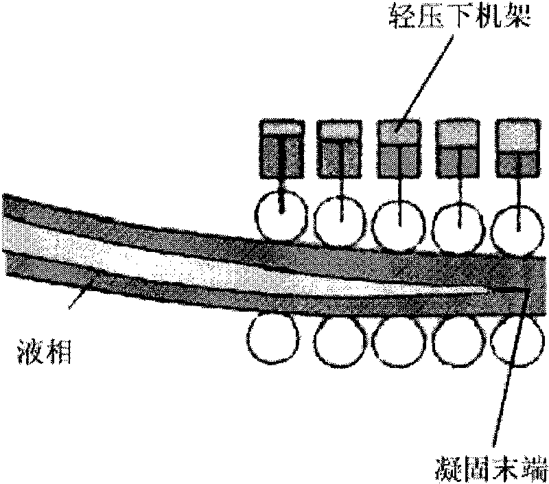
[0016] According to an embodiment of the present invention, the distances between the positions of the lightly depressing racks and the liquid surface of the pouring molten steel are shown in Table 1.

[0017] Table 1

[0018] Slightly press the rack number

Distance from pouring molten steel surface / m

1 #

21.851

2 #

23.351

3 #

24.851

4 #

26.351

5 #

27.951

6 #

29.551

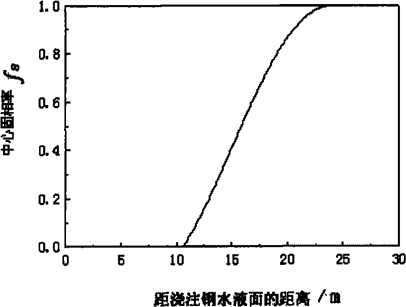
[0019] According to Table 1, each frame of the soft reduction equipment is set at a position 21.851-29.551m away from the pouring molten steel surface, that is to say, when the six soft reduction frames are all subjected to soft reduction, the area of ​​the soft reduction area The maximum length is 7.7m. In the light reduction area, it can be ensured that when the slab passes through this area, the central solid phase ratio is 0.2-0.95. The long soft reduction area can adapt to the change of solidification en...


PUM


Abstract

The invention relates to an axle steel continuous casting method. The method comprises the following steps of: pouring molten steel to a crystallizer from a pouring box to form an axle steel casting blank which is not fully solidified; and then withdrawing the axle steel casting blank which is not fully solidified from the crystallizer at a withdrawing speed v and sequentially going through a secondary cooling zone and an air cooling zone to obtain a fully solidified axle steel casting blank. The method also comprises a soft press process for utilizing at least one of the plurality of soft press stands sequentially arranged on the air cooling zone to perform soft reduction on the axle steel casting blank which is not fully solidified, and the central solid fraction fs of the axle steel casting blank which is not fully solidified in the soft press process is kept at 0.2 to 0.95. Soft press is carried out on the axle steel casting blank which is not fully solidified with the central solid fraction of 0.2 to 0.95, internal gaps formed by casting blank shrinkage can be eliminated or reduced to prevent the intergranular solute-enriched molten steel from laterally flowing to a casting blank center, and the intergranular solute- enriched molten steel of a liquid phase center is induced to flow along the opposite direction of the blanking withdrawing direction, solute elements are redistributed in the molten steel, and the center segregation is improved.

Description

technical field [0001] The invention relates to a continuous casting method, in particular to continuous casting of axle steel. Background technique [0002] Continuous casting is a commonly used iron and steel casting process at present. Specifically, the smelted molten steel is poured into the tundish (which can hold dozens of tons of molten steel), and the liquid molten steel flows vertically through the small holes under the tundish to the non-stop vibrating in the crystallizer. The mold is continuously cooled with high-pressure water, and the molten steel forms a solid state in the mold and a liquid state in the interior. Outside the crystallizer is an arc-shaped cooling roller table, on which the billet moves, and usually passes through the water-cooled zone and the air-cooled zone in sequence to obtain a solid cast billet. [0003] Axle is an important part of railway vehicle running, and its quality status is directly related to the carrying capacity and transporta...

Claims


Application Information

Patent Timeline
IPC IPC(8): B22D11/11B22D11/112B22D11/18
Inventor 陈永吴国荣曾建华杨素波周伟冯远超
Owner PANGANG GROUP RESEARCH INSTITUTE CO LTD
Learn More